DSC PowerSeries Neo User Manual
Dual path controller
Hide thumbs
Also See for PowerSeries Neo:
- Installation manual (52 pages) ,
- User manual (49 pages) ,
- Installation instructions manual (40 pages)
Table of Contents

Subscribe to Our Youtube Channel
Related Manuals for DSC PowerSeries Neo


Summary of Contents for DSC PowerSeries Neo
- Page 1 TL8803GI-EU Dual Path Controller WARNING: This manual contains information on limitations regarding product use and function and information on the limitations as to liability of the manufacturer. The entire manual should be carefully read.
-
Page 3: Table Of Contents
Table of Contents Warning: Installer Please Read Carefully Alarm.com introduction IP/HSPA 3G module - TL8803GI-EU Contact information Features Communicator ratings Communicator compatibility Installation Tools and supplies required Step 1: Enable module Step 2: Connect the TL8803GI-EU 1: Connect data bus 2: Connect power 3: Connect the PC-Link cable 4: Connect Ethernet (optional) -
Page 4: Warning: Installer Please Read Carefully
an attempted break-in, a fire, a storm, an earthquake, an accident, or Warning: Installer Please Read any kind of construction activity inside or outside the premises. The test- ing should include all sensing devices, keypads, consoles, alarm indic- Carefully ating devices, and any other operational devices that are part of the system. - Page 5 Telephone lines If telephone lines are used to transmit alarms, they may be out of ser- vice or busy for certain periods of time. Also an intruder may cut the telephone line or defeat its operation by more sophisticated means which may be difficult to detect.
-
Page 6: Alarm.com Introduction
IP/HSPA 3G module - TL8803GI-EU The Dual Path module enables wireless reporting of all alarms and other system events from the DSC Neo con- trol panel using an all-digital, HSPA wireless (cellular) network or an Ethernet network. The module can be used as the primary communication path for all alarm signaling, or as a backup to a telephone connection to the central monitoring station. -
Page 7: Contact Information
2-way audio capable when used with audio module HSM2955(R) - Refer to HSM2955(R) manual. Communicator ratings Model TL8803GI-EU Power supply ratings 11.3V - 12.5V DC Input Voltage (provided by DSC NEO compatible control panel) Current consumption Standby Current (Average Value) 100mA@12V (I) Alarm (Transmitting) Current (Peak Value) 200mA@12V (I) Cellular Network... -
Page 8: Communicator Compatibility
Communicator compatibility Receiver/ Communicator Description Panel Sur-Gard System I-IP Receiver, version 1.13+ Sur-Gard System II Receiver, version 2.10+ Receiver Sur-Gard SG-DRL3-IP, version 2.30+ (for Sur-Gard System III Receiver) Sur-Gard SG-DRL4-IP version 1.20+ (for Sur-Gard System IV Receiver) Sur-Gard SG-DRL5-IP version 1.00+ (for Sur-Gard System 5 Receiver) TL8803GI-EU HS2016, version 1.1+ HS2032, version 1.1+... -
Page 9: Installation
Installation NSTALLATION Follow these guidelines during installation. Before affixing the communicator to a wall, verify the HSPA signal level at the installation location. On a keypad, press and hold the 5 key for 2 seconds to view the HSPA signal level. An installation location with a sustained signal level of two or more bars is recommended. -
Page 10: Step 1: Enable Module
Installation Mounted in Alarm Controller Cabinet HSPA Controller Board +12V +12V PCL-422 A Red wire on alarm controller PCLink2 Header B Antenna access ports C Ethernet cable connection D Quad cables (100' / 30m maximum) E Red wire on PCL-422 PCLink Header F HSPA Controller Board power terminals. -
Page 11: 2: Connect Power
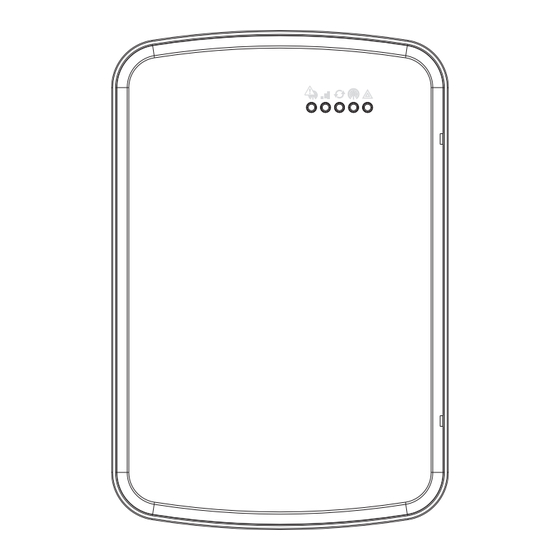
Upgraded antennas are available for the TL8803GI-EU if there is inadequate cellular reception at the pre- ferred mounting location. Contact DSC technical support for antenna options. The TL8803GI-EU has two covered access ports on the top of the enclosure. Remove the plastic tab covering the desired port and either mount the antenna on the enclosure or use the opening to pass through the antenna cable. -
Page 12: 6: Power Up
Installation 6: Power up Connect panel battery and AC power. Once powered, view key items on the LCD. Ensure that the module has been fully connected to the alarm panel via quad cable as shown in wiring diagram. Step 3: Verify installer code to activate Alarm.com module Alarms and other signals will not be sent to Alarm.com until the installer code is verified. -
Page 13: Panel Settings
By default, the Image Sensor is enrolled as an Interior Stay/Away zone in zone type 005. Zone type and attributes can be assigned in the installer menu, in a similar way as regular zones. For more information, refer to the "Zone Setup" section of the PowerSeries Neo Alarm Controller Reference Manual. Panel settings... - Page 14 Installation Section Option Description 311 [001] Partition 1 Call Direction - Alarm/Restore 311 [002] Partition 1 Call Direction - Tamper/Restore 311 [003] Partition 1 Call Direction - Opening/Closing 312 [001] Partition 2 Call Direction - Alarm/Restore 312 [002] Partition 2 Call Direction - Tamper/Restore 312 [003] Partition 2 Call Direction - Opening/Closing 313 [001]...
- Page 15 Installation Section Option Value Description Daylights saving time must be disabled to ensure panel time is accurate. Set according to Enables Duress Code changes from dealer's Alarm.com Alarm.com. setting Realtime clock must be disabled to ensure panel time is accurate. Swinger Shutdown for maintenance signals Swinger Shutdown must be set to 010 to ensure trouble...
-
Page 16: Troubleshooting
Troubleshooting ROUBLESHOOTING Module status information Module status information for verifying and troubleshooting the module connection status or errors can be found through the Interactive Services menus. To access these, press [*][8][Installer Code][851]. See the fol- lowing table for potential module states. Status Description Idle... -
Page 17: Led Functions
Troubleshooting Status LEDs L1 L2 L3 L4 L5 LED functions Function General & Cellular Error LED. Flashes 1 to 8 times in an 8-second interval to indicate specific error. See section “LED L1 (red)” for errors and common fixes. Broadband Errors & Panel Communication. Flashes 2 to 8 times in an 8-second interval to indicate a specific error on the broadband path. -
Page 18: Led L2 (Yellow)
Troubleshooting Number of Error and solution flashes The module is registered on the HSPA network but cannot connect with Alarm.com. Power down the module, wait one minute, restore power and perform a communications test. Verify signal strength and try a different location for the module/antenna. If the problem persists, contact Alarm.com Technical Support. -
Page 19: Led L5 (Yellow)
Troubleshooting LED L5 (yellow) LED L5 indicates Z-Wave state and errors. See the table below for more information. Number of flashes Device status or error Successfully added/removed node (last 60 seconds) Delete Mode Add node attempt failed (last 60 seconds) because device already in network Add Mode Replicate Mode Learn Mode Error (lasts 60 seconds) -
Page 20: Improving Wireless Signal Strength
Install the module near or adjacent to an exterior-facing wall of the structure. Do not install the module inside a metal structure or close to large metal objects or ducts. Upgrade the antenna. Contact DSC technical support for antenna options. Walking the customer through new user setup on the web This section describes how to help your customer set up their website account, and only applies to customers on an interactive service plan with an online account. -
Page 21: Interactive Service Menu
Interactive Service Menu NTERACTIVE ERVICE Interactive menus The “Interactive Services” menu can be used to access information about the TL8803GI module, install or remove Z-Wave devices and configure or troubleshoot other interactive features. The menu will time out after 20 minutes. Refer to the following tables for the menu options. Installer programming Press [*][8][Installer Code][851] to enter Interactive Services menu. - Page 22 Interactive Service Menu Menu Description ---HSPA Freq. See Installer Programming section --SN See Installer Programming section ---SIM card See Installer Programming section ---Version See Installer Programming section ---Advanced - Network See Installer Programming section --Z-Wave Setup See Installer Programming section ---Number of Z-Wave Devices See Installer Programming section ---Add Z-Wave Device...
-
Page 23: Limited Warranty
Warranty: (i) freight cost to the repair centre; charged for each replacement unit. (ii) products which are not identified with DSC's product label and lot number or serial number; (iii) products disassembled or repaired in... - Page 24 If You do not accompanying printed materials, and any copies of the SOFTWARE agree to the terms of this EULA, DSC is unwilling to license the PRODUCT, are owned by DSC or its suppliers. You may not copy the SOFTWARE PRODUCT to You, and You have no right to use it.
-
Page 25: Regulatory Information
INCLUDING CUSTOMERS, AND INJURY TO PROPERTY. the EU declaration of conformity is available at the following internet DSC recommends that the entire system be completely tested on a reg- address: ular basis. However, despite frequent testing, and due to, but not limited http://dsc.com/pdf/1609001... - Page 28 © 2017 Tyco Security Products. All Rights Reserved. Tech Support: 1-800-387-3630 (Canada & U.S.) or 905-760-3000 www.dsc.com The trademarks, logos, and service marks displayed on this document are registered in the United States and/or other countries. Any misuse of the trademarks is strictly prohibited and Tyco will aggressively enforce its intellectual property rights to the fullest extent of the law, including pursuit of criminal prosecution wherever necessary.
Need help?
Do you have a question about the PowerSeries Neo and is the answer not in the manual?
Questions and answers