Table of Contents
Advertisement
Quick Links
Advertisement
Table of Contents

Related Manuals for EAE EE62C-50T-E


Summary of Contents for EAE EE62C-50T-E
- Page 1 Model No. EE62C-50T-E Installation, Operation Two Post Lift ...
- Page 2 Installation, Operation and Parts Manual EE62C-50T-E IMPORTANT NOTES Before start up, connecting and operating EAE products, it is absolutely essential that the operating instructions/owner’s manual and, in particular the safety instructions are studied carefully. By doing so you can eliminate any uncertainties in handling EAE products and thus associated safety risks up front; something which is in the interest of you own safety and will ultimately help avoid damage to the device, When an EAE product is handed over to another person, not only the operating instructions but also the safety instructions and information on its designated use must be handed over to the person. By using the product you agree the following conditions: Copy right The enclosed instructions are the property of EAE or its supplier, and are protected against duplication and reproduction by copyright laws, international agreements, and other domestic legislation. The reproduction or disclosure of instructions or an extract thereof is prohibited and offenders are liable to prosecution; EAE reserves the right or initiates criminal proceedings and asserts claims for damages in the event of infringements. Warranty The use of non‐approved hardware will result in a modification of our products and thus to the exclusion of any liability or warranty, even if such hardware has been removed again in the interim. It is not permissible to make any changes to our products and these are not only to be used together with genuine accessories and genuine replacement parts. Otherwise any warranty claims will be invalid. Liability The liability of EAE is limit to the amount that the customer has actually paid for this product. This exclusion of liability does not apply to damages caused through willful misconduct or gross negligence on the part of EAE. All information in this manual is believed to be correct at time of publication. EAE reserves the right to amend and alter technical data and composition without prior notice. Please confirm at time of ordering. ...
-
Page 3: Table Of Contents
Installation, Operation and Parts Manual EE62C-50T-E IMPORTANT NOTES ............................ 2 SAFETY NOTES .............................. 4 1.1 Operation of lifting platforms .......................... 4 1.2 Checking of the lifting platforms .......................... 4 1.3 Important safety notices ............................ 5 1.4 Warning labels ............................... 6 1.5 Potential safety risks .............................. 7 1.6 Noise level ................................ 7 PACKING, STORAGE AND TRANSPORTATION ..................... 8 2.1 The lift was dismantled into the following 3 parts for transportation .............. 8 2.2 Storage ................................... 8 ... -
Page 4: Safety Notes
Installation, Operation and Parts Manual EE62C-50T-E SAFETY NOTES 1.1 Operation of lifting platforms This lift is specially designed for lifting motor vehicles. Users are not allowed to use it for any other purposes. The applicable national regulations, laws and directives must be observed. Only users aged 18 or above who have been instructed on how to operate the lifting platform and have proven their ability to do so to the owner are to be entrusted with unsupervised operation of lifting platforms. The task of operating the lifting platforms must be granted in writing. Before loading a vehicle onto the lift, users should study the original operation instructions and familiarize themselves with the operating procedures in several trial runs. Lift vehicle within the rated load. Don’t attempt to raise vehicles with excessive weight. 1.2 Checking of the lifting platforms Checks are to be based on the following directives and regulations: Basic principles for testing lifting platforms The basic health and safety requirements stipulated in the directive 2006/42/EC Harmonized European standards The applicable accident prevention regulations The checks are to be organized by the user of the lifting platform. The user is responsible for appointing an expert or qualified person to perform checking. It must be ensure that the person chosen satisfies the requirements. The user bears special responsibility if employees of the company are appointed as experts or qualified persons. 1.2.1 Scope of checking Regular checking essentially involves performing a visual inspection and a functional test. This includes checking the condition of the components and equipment, checking that the safety systems are complete and functioning properly and that the inspection log ... -
Page 5: Important Safety Notices
Installation, Operation and Parts Manual EE62C-50T-E rules of engineering to be able to check and give an expert option on lifting platforms. 1.3 Important safety notices 1.3.1 Recommend for indoor use only. DO not expose the lift to rain, snow or excessive moisture. 1.3.2 Only use this lift on a surface that is stable and capable of sustaining the load. Do not install the lift on any asphalt surface. 1.3.3 Read and understand all safety warnings before operating the lift. 1.3.4 Do not leave the controls while the lift is still in motion. 1.3.5 Keep hands and feet away from any moving parts. Keep feet clear of the lift when lowering. 1.3.6 Only these properly trained personnel can operate the lift. 1.3.7 Do not wear unfit clothes such as large clothes with flounces, tires, etc., which could be caught by moving parts of the lift. 1.3.8 To prevent evitable incidents, surrounding areas of the lift must be tidy and with nothing unconcerned. 1.3.9 The lift is simply designed to lift the entire body of vehicles, with its maximum weight within the lifting capacity. 1.3.10 Always insure the safety locks are engaged before any attempt to work near or under the vehicle. Never remove safety related components from the lift. Do not use if safety related components are damaged or missing. 1.3.11 Do not rock the vehicle while on the lift or remove any heavy component from vehicle that may cause excessive weight shift. 1.3.12 Check at any time the parts of the lift to ensure the agility of moving parts and the performance of synchronization. Ensure regular maintenance and if anything abnormal occurs, stop using the lift immediately and contact our dealers for help. 1.3.13 Lower the lift to its lowest position and do remember to cut off the power source when service finishes. 1.3.14 Do not modify any parts of the lift without manufacturer’s advice. 1.3.15 If the lift is going to be left unused for a long time, users are required to: a. Disconnect the power; b. Empty the oil tank; c. Lubricate the moving parts with hydraulic oil. WARNING:The warnings, cautions and instructions discussed in this instruction manual cannot cover all possible conditions and situations that may occur. It must be understood by the operator that common sense and caution are factors which cannot be built into this product, but must be supplied by the operator. ... -
Page 6: Warning Labels
Installation, Operation and Parts Manual EE62C-50T-E 1.4 Warning labels All safety warning labels are clearly depicted on the lift to ensure that the operator is aware of and avoid the dangers of using the lift in an incorrect manner. The labels must be kept clean and they have to be replaced if detached or damaged. Please read carefully the meaning of each label and memories them for future operation. ... -
Page 7: Potential Safety Risks
Installation, Operation and Parts Manual EE62C-50T-E 1.5 Potential safety risks 1.5.1 Main voltage nsulation damage and other faults may result in accessible components being live. Safety measures: Only ever use the power cord provided or a tested power cord. Replace wires with damaged insulation. Do not open the operating unit. 1.5.2 Risk of injury, danger of crushing In the event of excessive vehicle weight, incorrect mounting of the vehicle or on removing heavy object, there is a risk of the vehicle falling off or tipping up. Safety measures: The lift is only ever to be employed for the intended purpose. Carefully study and heed all the information given in Section 1.4. Observe the warning notices for operation. 1.6 Noise level Noise emitted during operating the lift should be less than 70dB(A). For your health consideration, it is suggested to place a noise ... -
Page 8: Packing, Storage And Transportation
Installation, Operation and Parts Manual EE62C-50T-E PACKING, STORAGE AND TRANSPORTATION Packing, lifting, handling, transporting operations must be performed only by experienced personnel with appropriate knowledge of the lift and after reading this manual. 2.1 The lift was dismantled into the following 3 parts for transportation Name Packed by Dimension(mm) Weight (kg) Quantity ( ) Lift Steel brackets 2860*660*930 approx. 930 1 Extending post Bubble film 1800*400*430 approx. 145 1 Power unit Carton 850*250*350 approx. 24 1 ... -
Page 9: Products Descriptions
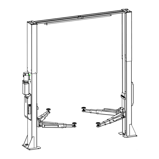
Installation, Operation and Parts Manual EE62C-50T-E PRODUCTS DESCRIPTIONS 3.1 General descriptions This is chassis supporting vehicle lift for road vehicles. It is mainly composed by two posts, two carriages, four swing arms and a power and control unit. It is driven by an electro‐hydraulic system. The gear pump delivers hydraulic oil to oil cylinders and pushes upwards its piston. The cylinder piston drives to raise the carriage and swing arms. It is equipped with mechanical safety locking unit which ensures no risks of slipping off in case of hydraulic failure. 3.2 Construction of the lift 1. Hydraulic power unit 2. Control unit 3. Crossbeam 4. Extending post 5.Steel cable 6. Hydraulic cylinder 7. Carriage 8.Swing arm 3.3 Technical data ... -
Page 10: Dimensions
Installation, Operation and Parts Manual EE62C-50T-E 3.4 Dimensions ... -
Page 11: Safety Devices Descriptions
Installation, Operation and Parts Manual EE62C-50T-E 3.5 Safety devices descriptions POS. Description Function 1 Steel cable Ensure sure the synchronization for both carriages 2 Mechanical safety locking unit Catch the carriages in case of hydraulic failure 3 ... -
Page 12: Installation Instructions
Installation, Operation and Parts Manual EE62C-50T-E INSTALLATION INSTRUCTIONS 4.1 Preparations before installation 4.1.1 Space requirements. Indoor installation only. Refer to 3.4 for the dimensions of the lift. There must also be a clearance of at least 1 meter between the lifting platform and fixed elements (e.g. wall) in all lifting positions. There must be sufficient space for driving vehicles on and off. 4.1.2 Foundations and connections The user must have the following work performed before erecting the lift. Construction of the foundation following consultation with the manufacturer’s customer service or an authorized service agent. Routing of the wiring to the installation location. The user must provide fuse protection for the connection. Electrical system 2 connection must be done by a qualified electrician. Requirements for power supply cable of the installation site: at least 2.5mm 2 wire core for 3Ph power and 4.0mm wire core for 1Ph power. Refer also to the corresponding information on the name plate and in the operation instructions. Before doing electrical connection, make sure the lift is electrically adapt to the local power supply. Foundations preparations (see Annex 1, floor plan) To ensure stability and safety under load, the lift shall be installed with the base frame being in direct and firm contact with the concrete foundation. Don't attempt to fix the base frame directly onto floor with ceramic and other decorated surfaces otherwise you put the lift into a very dangerous situation. C30 concrete foundation with a minimum thickness of 250mm. Surface under the base plates: Horizontal and even (Gradients max. 0.5 %). Newly built concrete ground must be older than 20days. 4.1.3 Tools and equipment needed for installation Tool name ... -
Page 13: General Installation Steps
Installation, Operation and Parts Manual EE62C-50T-E 4.2.3 Do not place any vehicle on the lift in the case of trial running. 4.3 General Installation Steps ONLY TRAINED AND QUALIFIED INSTALLERS CAN PERFORM LIFT INSTALLATION DUTIES. Step 1: Remove the packaging, take out the carton for accessories. Step 2: Firstly, put something supporting between the two posts or suspend one of the posts by a crane and then remove the bolts from the packing frame. Attention:Please pay special attention not to let the post fall down for it may cause casualty or bring damages to the accessories fixed in the post. Step 3: When the first post has been taken away, place something supporter under the second post and then remove the bolts from the packing frame. Step 4: Connect extending posts and cross beams 1. Firstly have the extending post firmly secured on to the body posts. This is only necessary when your lift is ordered with extending posts ... - Page 14 Installation, Operation and Parts Manual EE62C-50T-E 2. Connect the beams and fix the roof protection bumper 1.Self‐locking nut M6 2.Hex socket cylinder screw M6*35 3.Hex head screw M14*35 4.Flat washer M14 5.Spring washer M14 6.Hex nut M14 7.Car roof protective rod Step 5: Fix the standing position for the two posts. (See Annex 1, floor plan) 1. Unfold the package and decide on which post the power unit will be mounted. 2. Draw an outline of the base plate on the ground with chalk and ascertain the position for the post. Step 6: Connect cross beam. Make the posts face to each other and the distance between the posts equals to the length of the overhead crossbeam. Fix the beam to the posts by screw M12×30 ...
- Page 15 Installation, Operation and Parts Manual EE62C-50T-E Anchoring A1 A2 A3 B1 B2 C bolt (foundation thickness ) (drilling depth) (anchoring depth) M18x200 ≥200mm 160mm 145mm 200mm 320mm ≤55mm Step 8: Install the mechanical locking unit. Fix four safety locking plates and electromagnets with two of them on each post. ...
- Page 16 Installation, Operation and Parts Manual EE62C-50T-E Step 9: Connect steel cables. 1. Route and fix according to the following diagram of steel cable connection. 2. Use suitable means to raise carriages at both sides to the first latching point. Ensure the both carriages are locked. 3. After the cable being fixed, adjust and make the cables at both sides be with the same tension. (This could be judged by the sound caused by mechanical safety locking system during lifting process.) 4. Grease with NO.1 lithium grease (It is a must.) Step 10: Install the hydraulic system. Attention: Do not contaminate the hydraulic system when do the connection. 1. Mount the power unit onto the power side post. 1.Hex head full swivel screw M10x35 2.Power side post 3.Anti‐shock pad 4.Hydraulic power unit 5.Flat washer M10 6.Spring washer M10 7.Hex nut M10 ...
- Page 17 Installation, Operation and Parts Manual EE62C-50T-E 2. Connect oil hoses according to the following diagram. Don’t let any solid substance go into the hydraulic line. Ensure the connectors are screwed tight against leakage. 1.Oil hose 1 2.Hydraulic power unit 3.Oil hose 2 4.Oil hose 3 5.Hydraulic cylinder Step 10: Install the electrical system. Attention: ONLY qualified electricians are permitted to do the electrical connection. Refer to electrical connection diagram before making the connection. 1. Mount the control box on to the power side post. 1.control box 2.hex socket screw M6x15 3.post 2. Fix the limit switch onto the inside surface of the power side post. Connect the wire of limit switch with the terminals reserved in the control box. 1.Cross socket flat head screw M5x10 ...
- Page 18 Installation, Operation and Parts Manual EE62C-50T-E 3.Connect the limit switch fixed at the cross beam. 1.Cross socket flat head screw M4*25 2.Limit switch D4MC1000 4. Connect quick connectors between electromagnets. Adjustable bolt Quick connector 5. Connect the solenoid valve wire and motor wire. ...
- Page 19 Installation, Operation and Parts Manual EE62C-50T-E Step 11: Install lifting arms. Connect the lifting arm and the carriage. The arm pin shafts must be greased at the installation. Ensure the arm lock can engage and release effectively. . Attention: Install Lifting arms and fix feet protection bars ONLY after the complete assembly has been erected and anchored. 1.Carriage 2.Pin shaft 3.Long arm 4.Clip 5.Pull rod 6.Swing arm lock Step 13: Fill with hydraulic oil. CLEAN AND FRESH OIL ONLY. DON’T FILL THE TANK COMPLETELY FULL. Lift must be fully lowered before changing or adding hydraulic oil Pour 10 liters of anti‐abrasion hydraulic oil into the oil tank. The level of oil shall reach the tippets volume mark of the tank. Add more oil after running the lift for several cycles until the lift can rise to the maximum lifting height. It is suggested to use HM NO.46 hydraulic oil. When average temperature of the location is below 10℃, use HM NO.32 hydraulic oil. Change the oil 6 months after initial use and change once per year thereafter. Step 14: Trial running. Get familiar with lift controls by running the lift through a few cycles before loading vehicle on lift. This step is of particular importance for it can check if the oil hose is well connected. The connection is qualified when there is no abnormal sound or leakage ...
- Page 20 Installation, Operation and Parts Manual EE62C-50T-E Check the synchronization of lifting carriages. Ensure the synchronization by adjusting the steel cables at both sides. Make both cables be of the same tension. This could be judged by the sound emitted by the safety locking unit during lifting process. If the lift doesn't raise, the motor may turn in the wrong direction. In such event, interchange wires U, V in the connection box. Step 15: Fix the two covering sheets and two covers for electromagnets. 1.Hex nut M6 2.Flat washer M6 3.Hook 3.Covering sheet 5.Flat washer M6 6.Cross socket cap head screw M6x8 1.Hex socket screw M6x12 ...
-
Page 21: Items To Be Checked After Installation
Installation, Operation and Parts Manual EE62C-50T-E 4.4 Items to be checked after installation. S/N Check items YES NO 1 Screw torque of expansion bolts : 80‐100Nm; √ 2 Rising speed ≥20mm/s; √ 3 Noise with rated load ≤75dB(A); √ 4 Grounding resistance: not bigger than 4Ω; √ 5 Height difference of the two carriages ≤5mm; √ 6 Mechanical locks are robust and synchronized when running with rated load ; √ 7 If the control button works as “hold to run”? ... - Page 22 Installation, Operation and Parts Manual EE62C-50T-E Pos. Descriptions Function QS Power switch Control main power HL Power indicator Show if electricity is connected SB1 UP button Control the rising movement SB2 Safety lock button Engage the mechanical safety lock ...
-
Page 23: Trouble Shooting
Installation, Operation and Parts Manual EE62C-50T-E TROUBLE SHOOTING ATTENTION: If the trouble could not be fixed by yourself, please do not hesitate to contact us for help. We will offer our service at the earliest time we can. Troubles could be judged and solved much faster when more details or pictures could be provided. TROUBLES POSSIBLE CAUSES SOLUTIONS Abrasion exists on insider surface of the posts. Grease the inside of the post. Abnormal noise Trash in the post. Clear the trash Loose wire connection Check and make a good connection. Motor does not run and Blown motor. Replace it. will not rise Damaged limit switch or its wire connection is loose. Adjust or replace the limit switch. The motor run reversely. Check the wire connection. Overflow valve is not well screwed up or jammed. Clean or make adjustment Damaged gear pump. Replace it. Motor runs but will not raise Too low oil level. Add oil. The hose connection is loose. ... -
Page 24: Maintenance
Installation, Operation and Parts Manual EE62C-50T-E MAINTENANCE Following are requirements for routine maintenance. Easy and low cost routine maintenance can ensure the lift work normally and safely. Frequency of routine maintenance is determined by working condition and frequency. S/N Components Methods Period Push the UP button to raise the lifting arms and check if four swing 1 Swing arm locking units Every day arms are locked into position. Add grease in case necessary. Inspect the pads and clean off any objects that may cause sliding or 2 Rubber contact pads Every day damage Cylinder and oil hose 3 Inspect to ensure no leakage before using the lift. Every day connectors ... - Page 25 Installation, Operation and Parts Manual EE62C-50T-E S/N Components Methods Period Push the UP button and inspect and to ensure the lifting platform 6 Limit switch Every day stops rising when the switch is activated. 7 Unloading valve Inspect if the valve leaks or not. Clean or change the valve if it leaks. Every day Check the synchronization of both carriages and adjust the tension 8 Steel cables Every day of the cable when desynchronization is unacceptable. Bushing of the upside pulley Lubricate the bushing with NO.1 lithium based grease. 9 Every 3 months and circlip of the shaft ...
-
Page 26: Annex 1, Floor Plan
Installation, Operation and Parts Manual EE62C-50T-E Annex 1, Floor plan Indoor installation only. There must also be a clearance of at least 1 meter between the lifting platform and fixed elements (e.g. wall) in all lifting positions. There must be sufficient space for driving vehicles on and off. C30 concrete foundation with a minimum thickness of 250mm. Surface: Horizontal and even (Gradients max. 0.5 %) Newly built concrete ground must be older than 20days. In mm. ... -
Page 27: Annex 2, Electrical Diagrams And Parts List
Installation, Operation and Parts Manual EE62C-50T-E Annex 2, Electrical diagrams and parts list (Note: For the specific requirements on voltage, the actual voltage of your lift may differ with the following diagram) ... - Page 28 Installation, Operation and Parts Manual EE62C-50T-E ...
- Page 29 Installation, Operation and Parts Manual EE62C-50T-E : Limit switch for roof protection SQ2: Limit switch for maximum height YA1‐YA4: Electromagnet YV: Solenoid valve for descending Line quantity Yellow-Green Blue Other colors...
- Page 30 Installation, Operation and Parts Manual EE62C-50T-E Pos. CODE Description Qty T 320102013 Transformer (dual 380V220V) 1 T 320102014 Transformer (dual 400V230V) 1 T 320102015 Transformer (dual 415V240V) 1 QF 320801003 Circuit breaker 1 QF1 320803003 Circuit breaker 1 QF2 320803006 Circuit breaker 1 KM 320901011 ...
-
Page 31: Annex 3, Hydraulic Diagrams And Parts List
Installation, Operation and Parts Manual EE62C-50T-E Annex 3, Hydraulic diagrams and parts list 1.oil tank 2.oil sucking filter 3.gear pump 4.coupling 5.motor 6.hydraulic block 7.cushion valve 8.overflow valve 9.single way valve 10.solenoid valve for descending 11.flow control valve 12.tank cover 13.composite connector 14.oil cylinder ... - Page 32 Installation, Operation and Parts Manual EE62C-50T-E Pos. CODE Description Specification Qty 1 Power unit 1 2 ...
- Page 33 Installation, Operation and Parts Manual EE62C-50T-E Pos. Code Descriptions Specification Qty 320201001 AC motor 220V‐2.2KW ‐1PH‐50HZ‐2P 1 AC motor 320201002 230V‐2.2KW ‐1PH‐50HZ‐2P AC motor 1 320201003 240V‐2.2KW ‐1PH‐50HZ‐2P AC motor 320201004 380V‐2.2KW ‐3PH‐50HZ‐2P AC motor 320201005 400V‐2.2KW ‐3PH‐50HZ‐2P ...
- Page 34 Installation, Operation and Parts Manual EE62C-50T-E Pos. Code Descriptions Specification Qty AC motor 320201006 415V‐2.2KW ‐3PH‐50HZ‐2P AC motor 1 320204016 380V‐3.0KW ‐3PH‐50HZ‐2P AC motor 1 320204017 400V‐3.0KW ‐3PH‐50HZ‐2P AC motor 1 320204018 415V‐3.0KW ‐3PH‐50HZ‐2P AC motor 320203001 380V‐3.5KW ‐3PH‐50HZ‐2P AC motor 320203005 400V‐3.5KW ‐3PH‐50HZ‐2P AC motor 320203006 415V‐3.5KW ‐3PH‐50HZ‐2P 2 330404006 ...
-
Page 35: Annex 4 , Mechanically Exploded Drawings And Parts List
Installation, Operation and Parts Manual EE62C-50T-E Annex 4 , Mechanically exploded drawings and parts list Pos. Code Description Specification Qty 1 615016001C Steel cable L=12530 2 2 203101012 Hex nut M20 8 3 204101011 Flat washer φ20 4 4 201201008 Expansion bolt M18*200 10 ... - Page 36 Installation, Operation and Parts Manual EE62C-50T-E Pos. Code Description Specification Qty 1 615017013 Oil cylinder 6264‐A24 2 2 624002005B Oil hose L=10100mm 1 3 410170101B Ring for cylinder fixation 6264‐A24‐B1 2 4 203103005 Hex locking nut M6 2 5 202109096 Hex socket cylinder head screw ...
- Page 37 Installation, Operation and Parts Manual EE62C-50T-E...
- Page 38 Installation, Operation and Parts Manual EE62C-50T-E Pos. Code Description Specification Qty 1 614016006 Inside beam 6215E‐A10‐B2 1 2 410160023 Rod 6215E‐A10‐B3 1 3 203103005 Hex locking nut M6 1 4 202109024 Hex head full swivel screw M6*35 1 5 201102035 Hex head full swivel screw ...
- Page 39 Installation, Operation and Parts Manual EE62C-50T-E Pos. Code Description Specification Qty 40 202111007 Hex socket flat head screw M8*20 8 41 420130010 Rund rubber pad 6214EKZ‐A4‐B4‐C4 4 42 615035037 Lifting tray 6214EKZ‐A4‐B4 4 43 202109040 Hex socket cylinder head screw M10*15 4 44 614013213B Retractable arm ...
- Page 40 Installation, Operation and Parts Manual EE62C-50T-E Pos. Code Description Specification Qty 1 206201004 Cotter pin M3*45 2 2 410010031 Washer 6254E‐A1‐B3 2 3 205101008 Bushing 2518 2 4 410130051 Pulley 6255E‐A1‐B2 2 5 206102008 Elastic cylinderical pin ...
Need help?
Do you have a question about the EE62C-50T-E and is the answer not in the manual?
Questions and answers