Table of Contents
Advertisement
Quick Links
Advertisement
Table of Contents

Related Manuals for EAE EE62C-35T-E


Summary of Contents for EAE EE62C-35T-E
- Page 1 Model No. EE62C-35T-E / EE62C-42T-E Installation, Operation Two Post Lift and Parts Manual Electrical Release Lifting Capacity 3500KG/4200KG Distributed by Please read this entire manual carefully and completely before installation or operation of the lift. DATE: 12/03/2021...
-
Page 2: Important Notes
Liability The liability of EAE is limit to the amount that the customer has actually paid for this product. This exclusion of liability does not apply to damages caused through willful misconduct or gross negligence on the part of EAE. -
Page 3: Table Of Contents
Installation, Operation and Parts Manual EE62C-35T-E / EE62C-42T-E IMPORTANT NOTES ............................2 SAFETY NOTES ..............................4 1.1 Operation of lifting platforms ..........................4 1.2 Checking of the lifting platforms ..........................4 1.3 Important safety notices ............................5 1.4 Warning labels ............................... 6 1.5 Potential safety risks .............................. -
Page 4: Safety Notes
Installation, Operation and Parts Manual EE62C-35T-E / EE62C-42T-E SAFETY NOTES 1.1 Operation of lifting platforms This lift is specially designed for lifting motor vehicles. Users are not allowed to use it for any other purposes. The applicable national regulations, laws and directives must be observed. -
Page 5: Important Safety Notices
Installation, Operation and Parts Manual EE62C-35T-E / EE62C-42T-E rules of engineering to be able to check and give an expert option on lifting platforms. 1.3 Important safety notices 1.3.1 Recommend for indoor use only. DO not expose the lift to rain, snow or excessive moisture. -
Page 6: Warning Labels
Installation, Operation and Parts Manual EE62C-35T-E / EE62C-42T-E 1.4 Warning labels All safety warning labels are clearly depicted on the lift to ensure that the operator is aware of and avoid the dangers of using the lift in an incorrect manner. The labels must be kept clean and they have to be replaced if detached or damaged. Please read carefully... -
Page 7: Potential Safety Risks
Installation, Operation and Parts Manual EE62C-35T-E / EE62C-42T-E 1.5 Potential safety risks 1.5.1 Main voltage nsulation damage and other faults may result in accessible components being live. Safety measures: Only ever use the power cord provided or a tested power cord. -
Page 8: Packing, Storage And Transportation
Installation, Operation and Parts Manual EE62C-35T-E / EE62C-42T-E PACKING, STORAGE AND TRANSPORTATION Packing, lifting, handling, transporting operations must be performed only by experienced personnel with appropriate knowledge of the lift and after reading this manual. 2.1 The lift was dismantled into the following 3 parts for transportation... -
Page 9: Products Descriptions
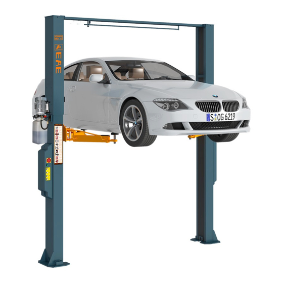
Installation, Operation and Parts Manual EE62C-35T-E / EE62C-42T-E PRODUCTS DESCRIPTIONS 3.1 General descriptions This is chassis supporting vehicle lift for road vehicles. It is mainly composed by two posts, two carriages, four swing arms and a power and control unit. -
Page 10: Dimensions
Installation, Operation and Parts Manual EE62C-35T-E / EE62C-42T-E 3.4 Dimensions Four pieces of two-stage arm... - Page 11 Installation, Operation and Parts Manual EE62C-35T-E / EE62C-42T-E Four pieces of three-stage arm Two pieces of three-stage arm and two pieces of two-stage arm...
-
Page 12: Safety Devices Descriptions
Installation, Operation and Parts Manual EE62C-35T-E / EE62C-42T-E 3.5 Safety devices descriptions POS. Description Function Steel cable Ensure sure the synchronization for both carriages Mechanical safety locking unit Catch the carriages in case of hydraulic failure Limit switch Stop rising movement at maximum safety height... -
Page 13: Installation Instructions
Installation, Operation and Parts Manual EE62C-35T-E / EE62C-42T-E INSTALLATION INSTRUCTIONS 4.1 Preparations before installation 4.1.1 Space requirements. Indoor installation only. Refer to 3.4 for the dimensions of the lift. There must also be a clearance of at least 1 meter between the lifting platform and fixed elements (e.g. -
Page 14: General Installation Steps
Installation, Operation and Parts Manual EE62C-35T-E / EE62C-42T-E 4.2.3 Do not place any vehicle on the lift in the case of trial running. 4.3 General Installation Steps ONLY TRAINED AND QUALIFIED INSTALLERS CAN PERFORM LIFT INSTALLATION DUTIES. Step 1: Remove the packaging, take out the carton for accessories. - Page 15 Installation, Operation and Parts Manual EE62C-35T-E / EE62C-42T-E 2. Connect the beams and fix the roof protection bumper 1.Self-locking nut M6 2.Hex socket cylinder screw M6*35 3.Hex head screw M14*35 4.Flat washer M14 5.Spring washer M14 6.Hex nut M14 7.Car roof protective rod Step 5: Fix the standing position for the two posts.
- Page 16 Installation, Operation and Parts Manual EE62C-35T-E / EE62C-42T-E Expansion anchoring bolt Equalizing plate Anchoring bolt (foundation thickness ) (drilling depth) (anchoring depth) M18x160 ≥200mm 130mm 105mm 240mm ≤55mm Step 8: Install the mechanical locking unit. Fix four safety locking plates and electromagnets with two of them on each post.
- Page 17 Installation, Operation and Parts Manual EE62C-35T-E / EE62C-42T-E Step 9: Connect steel cables. 1. Route and fix according to the following diagram of steel cable connection. 2. Use suitable means to raise carriages at both sides to the first latching point. Ensure the both carriages are locked.
- Page 18 Installation, Operation and Parts Manual EE62C-35T-E / EE62C-42T-E 2. Connect oil hoses according to the following diagram. Don’t let any solid substance go into the hydraulic line. Ensure the connectors are screwed tight against leakage. Step 11: Install the electrical system.
- Page 19 Installation, Operation and Parts Manual EE62C-35T-E / EE62C-42T-E 2. Fix the limit switch onto the inside surface of the power side post. Connect the wire of limit switch with the terminals reserved in the control box. 1.Cross socket flat head screw M5*10 2.Limit switch TZ8108...
- Page 20 Installation, Operation and Parts Manual EE62C-35T-E / EE62C-42T-E 5. Connect the solenoid valve wire and motor wire. Step 12: Install lifting arms. Connect the lifting arm and the carriage. The arm pin shafts must be greased at the installation Ensure the arm lock can engage and release effectively.
- Page 21 Installation, Operation and Parts Manual EE62C-35T-E / EE62C-42T-E Step 14: Trial running. Get familiar with lift controls by running the lift through a few cycles before loading vehicle on lift. This step is of particular importance for it can check if the oil hose is well connected. The connection is qualified when there is no abnormal sound or leakage after having been tested for 5-6 times.
-
Page 22: Items To Be Checked After Installation
Installation, Operation and Parts Manual EE62C-35T-E / EE62C-42T-E Step 16: Fix door-opening protecting pads and feet protection fenders. . 1.Cross socket flat head screw M8*16 2.Door protecting pad 3.Hex socket button head screw M8*12 4.Feet protecting fender 5.Lifting adapter 4.4 Items to be checked after installation. -
Page 23: Operation Instructions
Installation, Operation and Parts Manual EE62C-35T-E / EE62C-42T-E OPERATION INSTRUCTIONS 5.1 Precautions ·ONLY authorized persons are permitted in the lift area. ·Do not try to raise the vehicle with excessive length or width. Otherwise there is risk of vehicle falling from lift. - Page 24 Installation, Operation and Parts Manual EE62C-35T-E / EE62C-42T-E Raise the lift Make sure vehicle is neither front nor rear heavy and center of balance should be midway between adapters and centered over the lift. 1. Park the vehicle between two posts.
-
Page 25: Trouble Shooting
Installation, Operation and Parts Manual EE62C-35T-E / EE62C-42T-E TROUBLE SHOOTING ATTENTION: If the trouble could not be fixed by yourself, please do not hesitate to contact us for help. We will offer our service at the earliest time we can. -
Page 26: Maintenance
Installation, Operation and Parts Manual EE62C-35T-E / EE62C-42T-E MAINTENANCE Following are requirements for routine maintenance. Easy and low cost routine maintenance can ensure the lift work normally and safely. Frequency of routine maintenance is determined by working condition and frequency. - Page 27 Installation, Operation and Parts Manual EE62C-35T-E / EE62C-42T-E Components Methods Period Unloading valve Inspect if the valve leaks or not. Clean or change the valve if it leaks. Every day Check the synchronization of both carriages and adjust the tightness...
-
Page 28: Annex 1, Floor Plan
Installation, Operation and Parts Manual EE62C-35T-E / EE62C-42T-E Annex 1, Floor plan Indoor installation only. There must also be a clearance of at least 1 meter between the lifting platform and fixed elements (e.g. wall) in all lifting positions. There must be sufficient space for driving vehicles on and off. -
Page 29: Annex 2, Electrical Diagrams And Parts List
Installation, Operation and Parts Manual EE62C-35T-E / EE62C-42T-E Annex 2, Electrical diagrams and parts list (Note: For the specific requirements on voltage, the actual voltage of your lift may differ with the following diagram) - Page 30 Installation, Operation and Parts Manual EE62C-35T-E / EE62C-42T-E...
- Page 31 Installation, Operation and Parts Manual EE62C-35T-E / EE62C-42T-E : Limit switch for roof protection SQ2: Limit switch for maximum height YA1-YA4: Electromagnet YV: Solenoid valve for descending...
- Page 32 Installation, Operation and Parts Manual EE62C-35T-E / EE62C-42T-E Supply cable Yellow-Green Blue Other colors 3 wires Earth wire Neutral wire Phase wire 5 wires Earth wire Neutral wire Phase wire Supply cable Yellow-Green Other colors 4 wires Earth wire Phase wire Pos.
-
Page 33: Annex 3, Hydraulic Diagrams And Parts List
Installation, Operation and Parts Manual EE62C-35T-E / EE62C-42T-E Annex 3, Hydraulic diagrams and parts list 1.oil tank 2.oil sucking filter 3.gear pump 4.coupling 5.motor 6.hydraulic block 7.cushion valve 8.overflow valve 9.single way valve 10.solenoid valve for descending 11.flow control valve 12.tank cover... - Page 34 Installation, Operation and Parts Manual EE62C-35T-E / EE62C-42T-E Pos. CODE Description Specification Power unit 400V-50Hz-2.2kW 207103019 Composite washer 310101008 Shift connector M14*1.5-G1/4 inside cone 624008046 Oil hose Φ8.,L=320mm 615006003 Three way connector 6214E-A4-B4 624002003B Rubber oil hose L=8435 624002004B Rubber oil hose...
- Page 35 Installation, Operation and Parts Manual EE62C-35T-E / EE62C-42T-E Pos. Code Descriptions Specification 320201001 AC motor 220V-2.2KW -1PH-50HZ-2P AC motor 320201002 230V-2.2KW -1PH-50HZ-2P AC motor 320201003 240V-2.2KW -1PH-50HZ-2P AC motor 320201004 380V-2.2KW -3PH-50HZ-2P...
- Page 36 Installation, Operation and Parts Manual EE62C-35T-E / EE62C-42T-E Pos. Code Descriptions Specification AC motor 320201005 400V-2.2KW -3PH-50HZ-2P AC motor 320201006 415V-2.2KW -3PH-50HZ-2P 330404006 Coupling 48mm(YBZ-F2.1D4H1/1-03) 203204102 Locking nut FHLM-1/2-20UNF 330311005 Solenoid valve 24DC(Keta)(LSV-08-2NCP-M-2H) 330302008 Non-return valve YBZ-E2D3I1/1-03 330101113 Hydraulic block...
-
Page 37: Annex 4 , Mechanically Exploded Drawings And Parts List
Installation, Operation and Parts Manual EE62C-35T-E / EE62C-42T-E Annex 4 , Mechanically exploded drawings and parts list Pos. CODE Description Specification 615001061 Steel cable 62C-A6 L=10900±10mm 615001061 Steel cable 62C-A6 L=10900±10mm 203101009 Hex nut 204101009 Flat washer 201201007 Expansion bolt... - Page 38 Installation, Operation and Parts Manual EE62C-35T-E / EE62C-42T-E Pos. CODE Description Specification 615017013 Oil cylinder 6264-A24 624002003B Oil hose L=8435 410170101B Ring for cylinder fixation 6264-A24-B1 203103005 Hex locking nut 202109024 Hex head full swivel screw M6*35 615006003 Three way connector...
- Page 39 Installation, Operation and Parts Manual EE62C-35T-E / EE62C-42T-E Pos. CODE Description Specification 614006005B Crossbeam(in) 6214E-A21-B1 410060013 Top protective bar 6214E-A21-B5...
- Page 40 Installation, Operation and Parts Manual EE62C-35T-E / EE62C-42T-E Pos. CODE Description Specification 203103005 Hex locking nut 202109024 Hex head full swivel screw M6*35 201102035 Hex head full swivel screw M14*30 204101008 Flat washer 204201007 Spring washer 203101008 Hex nut 420060010...
- Page 41 Installation, Operation and Parts Manual EE62C-35T-E / EE62C-42T-E Pos. CODE Description Specification 420040250 Round lifting pad 6254E-A7-B4-C4 615004003D Lifting tray assembly 6254E-A7-B4 614004006C Long tensile arm 6254E-A7-B3 614004005B Long support arm 6254E-A7-B1 202110004 Hex socket button head screw M8*12 614004014B...
- Page 42 Installation, Operation and Parts Manual EE62C-35T-E / EE62C-42T-E Pos. CODE Description Specification 205101007 Bearing 2512 420010010 Slider 6254E-A2-B5 410044401B Pulling rod 6254E-A2-B1 410150121 Pressure spring 6254E-A2-B4 410901075 Teeth block 6254E-A2-B9 206102013 Elastic post pin D6X40-GB879 204301009 Circlip D25-GB894_2 410049031B Shaft...
- Page 43 Installation, Operation and Parts Manual EE62C-35T-E / EE62C-42T-E Optional 3-stage arm (615-1150,745-1345) Pos. CODE Description Specification 202109085 Hex socket cylinder head screw M12*30 410901074 Semi Teeth block 6254E-A7-B8 202109040 Hex socket cylinder head screw M10*15 202109040 Hex socket cylinder head screw...
- Page 44 Installation, Operation and Parts Manual EE62C-35T-E / EE62C-42T-E Optional quick arm POS. Code Description Specification 202109085 Hex socket cylinder head screw M12*30 410901074 Semi Teeth block 6254E-A7-B8 614004005 Long arm 6254E-A7-B1 614004008 Short arm 6254E-A08-B01 614004014B Long arm fender 6254E-A7-B5...
Need help?
Do you have a question about the EE62C-35T-E and is the answer not in the manual?
Questions and answers