Table of Contents
Advertisement
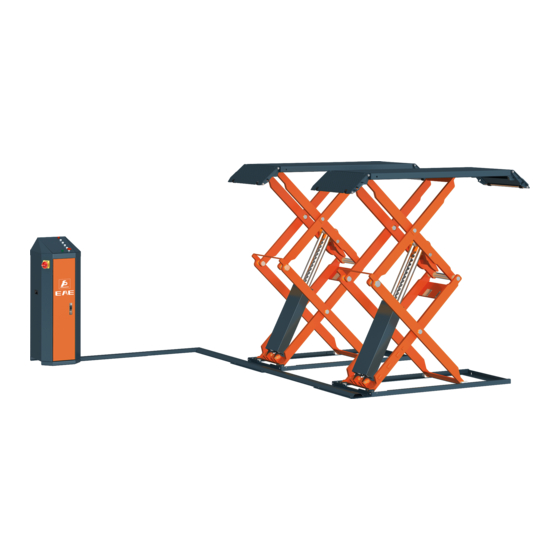
Model No. EE-6501V2
Short platform scissor lift
Low profile
Manual Leveling
With synchronization protection
Lifting capacity: 3000KG
Please read this entire manual carefully and completely before installation or operation of the lift.
Distributed by
Installation, Operation
and Parts Manual
Date: 27/10/2017
Advertisement
Table of Contents

Related Manuals for EAE EE-6501V2


Summary of Contents for EAE EE-6501V2
- Page 1 Model No. EE-6501V2 Installation, Operation ...
-
Page 2: Important Notes
Installation, Operation and Parts Manual EE-6501V2 IMPORTANT NOTES Before start up, connecting and operating EAE products, it is absolutely essential that the operating instructions/owner’s manual and, in particular the safety instructions are studied carefully. By doing so you can eliminate any uncertainties in handling EAE products and thus associated safety risks up front; something which is in the interest of you own safety and will ultimately help avoid damage to the device, When an EAE product is handed over to another person, not only the operating instructions but also the safety instructions and information on its designated use must be handed over to the person. By using the product you agree the following conditions: Copy right The enclosed instructions are the property of EAE or its supplier, and are protected against duplication and reproduction by copyright laws, international agreements, and other domestic legislation. The reproduction or disclosure of instructions or an extract thereof is prohibited and offenders are liable to prosecution; EAE reserves the right or initiates criminal proceedings and asserts claims for damages in the event of infringements. Warranty The use of non‐approved hardware will result in a modification of our products and thus to the exclusion of any liability or warranty, even if such hardware has been removed again in the interim. It is not permissible to make any changes to our products and these are not only to be used together with genuine accessories and genuine replacement parts. Otherwise any warranty claims will be invalid. Liability The liability of EAE is limit to the amount that the customer has actually paid for this product. This exclusion of liability does not apply to damages caused through willful misconduct or gross negligence on the part of EAE. ... -
Page 3: Table Of Contents
Installation, Operation and Parts Manual EE-6501V2 IMPORTANT NOTES .................................... 2 SAFETY NOTES ...................................... 4 1.1 Operation of lifting platforms .................................. 4 1.2 Checking of the lifting platforms ................................ 4 1.3 Important safety notices ..................................... 5 1.4 Warning labels ...................................... 6 1.5 Potential safety risks .................................... 7 1.6 Noise level ........................................ 7 PACKING, STORAGE AND TRANSPORTATION ............................ 8 2.1 The lift was dismantled into the following 2 parts for transportation ...................... 8 2.2 Storage ........................................ 8 2.3 Lifting and handling .................................... 8 PRODUCT DESCRIPTIONS .................................. 9 ... -
Page 4: Safety Notes
Installation, Operation and Parts Manual EE-6501V2 SAFETY NOTES 1.1 Operation of lifting platforms This lift is specially designed for lifting motor vehicles. Users are not allowed to use it for any other purposes. The applicable national regulations, laws and directives must be observed. Only users aged 18 or above who have been instructed on how to operate the lifting platform and have proven their ability to do so to the owner are to be entrusted with unsupervised operation of lifting platforms. The task of operating the lifting platforms must be granted in writing. Before loading a vehicle onto the lifting platform, users should study the original operation instructions and familiarize themselves with the operating procedures in several trial runs. Lift vehicle within the rated load. Don’t attempt to raise vehicles with excessive weight. A B C D E F G (mm) (mm) (mm) (T) ... -
Page 5: Important Safety Notices
Installation, Operation and Parts Manual EE-6501V2 A qualified person is somebody with the training and experience required to possess sufficient knowledge of lifting platforms and who is sufficiently familiar with the pertinent national regulations, accident prevention regulations and generally acknowledged rules of engineering to be able to assess the safe operating condition of lifting platforms. 1.2.3 Exceptional checking Lifting platforms with a lift height of more than 2 meters and lifting platforms intended for use with people standing under the load bearing elements of the load are to be checked by an expert prior or reuse following structural modifications and major repairs to load bearing components. An expert is somebody with the training and experience required to possess specialist knowledge of lifting platforms and who is sufficiently familiar with the pertinent national work safety regulations, accident prevention regulations and generally acknowledged rules of engineering to be able to check and give an expert option on lifting platforms. 1.3 Important safety notices 1.3.1 Recommed for indoor use only, DO not expose the lift to rain, snow or excessive moisture. 1.3.2 Only use this lift on a surface that is stable, level and dry and not slippery ,and capable of susutaining the load. Do not install the lift on any asphalt surface. 1.3.3 Read and understand all safety warnings before operating the lift. 1.3.4 Do not leave the controls while the lift is still in motion. 1.3.5 Keep hands and feet away from any moving parts. Keep feet clear of the lift when lowering. 1.3.6 Only these properly trained personnel can operate the lift. 1.3.7 Do not wear unfit clothes such as large clothes with flounces, tires, etc, which could be caught by moving parts of the lift. 1.3.8 To prevent evitable incidents, surrounding areas of the lift must be tidy and with nothing unconcerned. 1.3.9 The lift is simply designed to lift the entire body of vehicles, with its maximum weight within the lifting capacity. ... -
Page 6: Warning Labels
Installation, Operation and Parts Manual EE-6501V2 situations that may occur. It must be understood by the operator that common sense and caution are factors which cannot be built into this product, but must be supplied by the operator. Attention: For environment protection, please dispose the disused oil in a proper way. 1.4 Warning labels All safety warning labels are clearly depicted on the lift to ensure that the operator is aware of and avoid the dangers of using the lift in an incorrect manner. The labels must be kept clean and they have to be replaced if detached or damaged. Please read carefully the meaning of each label and memories them for future operation ... -
Page 7: Potential Safety Risks
Installation, Operation and Parts Manual EE-6501V2 1.5 Potential safety risks 1.5.1 Mains voltage nsulation damage and other faults may result in accessible components being live Safety measures: Only ever use the power cord provided or a tested power cord. Replace wires with damaged insulation. Do not open the operating unit. 1.5.2 Risk of injury, danger of crushing In the event of excessive vehicle weight, incorrect mounting of the vehicle or on removing heavy object, there is a risk of the vehicle falling off the lifting platform or tipping up. Safety measures: The lifting platform is only ever to be employed for the intended purpose. Carefully study and heed all the information given in Section 1.4. Observe the warning notices for operation. ... -
Page 8: Packing, Storage And Transportation
Installation, Operation and Parts Manual EE-6501V2 PACKING, STORAGE AND TRANSPORTATION Packing, lifting, handling, transporting operations must be performed only by experienced personnel with appropriate knowledge of the lift and after reading this manual. 2.1 The lift was dismantled into the following 2 parts for transportation Name Packed by Dimension(mm) Weight(kg) Quantity Control cabinet Wooden case 580*510*1010 100 1 Lift platforms Carton with wooden base 2050*700*400 800 1 2.2 Storage The packs must be kept in a covered and protected area in a temperature range 0f ‐10℃to +40℃. They must not be exposed to direct sunlight, rain or water. Stacking the packs We advise against stacking because the packs are not designed for this type of storage. The narrow base, heavy weight and large size of ... -
Page 9: Product Descriptions
Installation, Operation and Parts Manual EE-6501V2 PRODUCT DESCRIPTIONS 3.1 General descriptions This full rise scissor lift is of pretty lower profile when at its lowest position. Its four cylinder structure makes the lowest clearance from ground is 110mm. This model is designed with two different leveling systems‐auto leveling and manual leveling. For it is specially designed for surface mounting, users could have it installed with great convenience. Its platform extension deign not only can be used as a ramp, but also can serve as an extended part of the platform for much longer vehicles. Besides, designs like, 24V working voltage of control box and limit switch, alarming buzzer, pneumatic safety lock, anti‐surge valves, etc. have fully considered your personal security. 3.2 Construction of the lift ... -
Page 10: Dimensions
Installation, Operation and Parts Manual EE-6501V2 3.3 Dimensions Unit: mm ... -
Page 11: Safety Devices Descriptions
Installation, Operation and Parts Manual EE-6501V2 3.4 Safety devices descriptions POS. Safety device Function 1 24V operation voltage Safety voltage for operators. Ensure the lifting platform stop rising when reach a height of 1850mm above the 2 Max height limit switch ground. The lifting platforms automatically stop lowering at safety height above the ground. It needs to push DOWN II button to continue the lowering movement, 3 Safety lowering height limit switch meanwhile alarming buzzer will be heard warning service persons being away from the moving parts. 4 Mechanical lock Protect the lifting platform from falling down in case of failed hydraulic system. 5 Infrared synchronization protection ... -
Page 12: Technical Data
Installation, Operation and Parts Manual EE-6501V2 3.5 Technical data Rated load capacity 3000KG Full rise height 1850mm Full lowered height 110mm Full rise time with load ≤50s Full lowering time with load ≤30s Hydraulic pressure 22‐24MPa Pneumatic pressure 6‐8bar Oil Volume 18L INSTALLATION INSTRUCTIONS 4.1 Preparations before installation 4.1.1 Space requirements. Refer to 3.3 for the dimensions of the lift. There must also be a clearance of at least 1 meter between the lifting platform and fixed elements (e.g. wall) in all lifting positions. There must be sufficient space at the ends of the lifting platform for driving vehicles on and off. ... - Page 13 Installation, Operation and Parts Manual EE-6501V2 4.1.3 Foundations preparations C20/25 concrete base with strength more than 3000psi, tolerance of flatness less than 5mm and minimum thickness of 150mm. In addition, newly built concrete ground must be older than 20days. ...
- Page 14 Installation, Operation and Parts Manual EE-6501V2 4.1.4 Tools and equipment needed for installation Tool name Specification Quantity needed Electrical drill With D16 and D18 drill bit. 1 Open spanner D17‐19mm 2 Adjustable spanner bigger than D30mm 1 Cross socket screw driver PH2 1 Quick spanner handle adapter/ Ratchet 1 Socket spanner D24mm 1 Levelling device 1mm accuracy 1 Hammer 10 pounds ...
-
Page 15: Installation Attentions
Installation, Operation and Parts Manual EE-6501V2 4.2 Installation attentions 4.2.1 Joints of oil hose and wiring must be firmly connected in order to avoid leakage of oil hose and looseness of electrical wires. 4.2.2 All bolts should be firmly screwed up. 4.2.3 Do not place any vehicle on the lift in the case of trial running. 4.3 General Installation Steps Step 1: Dismantle the package of the lifting platforms. Remove the carton and packing films wrapped on the platform. Attention1: Take off oil hose protectors when cut off the packing strips. Attention 2: Avoid scratching the painting surface and hoses. Step 2: Place the lifting platform at expected installation site. Raise the upper platform by using a forklift and 2 lifting strings until the mechanical lock is engaged. And then hoist the platform onto the expected installation site. (Refer to the following fig. 1and2) Dismantle the bolts that fix the lower platform and its wooden package and move it to the installation site in the same way as the upper platform. Attention1: Before hoisting, make sure the hoses and wires are well protected against damage. Attention 2: It is necessary to hold the platform during the hoisting process. Irrelevant person is not allowed in installation area. ... - Page 16 Installation, Operation and Parts Manual EE-6501V2 Step 5: Connect the electrical system. 2 2 Requirements for power supply cable of the installation site: at least 2.5mm wire core for 3Ph power and 4.0mm wire core for 1Ph power. Refer to Annex 1 when fix the electrical system. Connect the wire connectors for rising and lowering limit switches Connect the power suppler cable to external electricity supply. (For three phase power supply ,if the lift doesn't raise and the motor may turn in the wrong direction, in such event, interchange wires U, V in the control cabinet) . Step 6: Connect the pneumatic release system. Screw torque for connector is 20N*M. Connect air hoses as per the following fig. External compressed air shall be prepared by the end user before installation. Pneumatic pressure 6 kg/cm²‐8kg/cm² ...
- Page 17 Installation, Operation and Parts Manual EE-6501V2 Step 7: Fill with hydraulic oil. CLEAN AND FRESH OIL ONLY. DON’T FILL THE TANK COMPLETELY FULL. Lift must be fully lowered before changing or adding hydraulic oil Pour 18 liters HM32 anti‐abrasion hydraulic oil into the oil tank. The level of oil shall reach the tippets volume mark of the tank. Add more oil after running the lift for several cycles until the lift can rise to the maximum lifting height. Note:As running speed of the lift is mainly decided by the viscosity of the hydraulic oil, we suggest using NO.46 hydraulic oil when average temperature of the location is above 18 degree Celsius and using NO.32 hydraulic oil when temperature is below 18 degree Celsius. Change the oil 6 month after initial use and change once per year thereafter. Step 8: Leveling Refer to 5.4 operation instructions and turn off the infrared switch before leveling operation Attention: Level the platforms before connecting height limit switch because if not, platforms cannot rise to the highest position. ...
- Page 18 Installation, Operation and Parts Manual EE-6501V2 A.5. In case they do not lower synchronously, open the valve that controls the slower‐lowering platform and press DWON I button to have them lowered to the lowest position and then close the leveling valve. If the lift is equipped with a height limit switch, press DOWN II button when platforms stop lowering at a safety height from the ground. A.6. After both leveling valves having been closed, press the UP button to check if both platforms rise synchronously. A.7. Repeat doing step A5 and step A 6 until synchronization achieved. Step 9: Fix base frames with expansion bolts. 1. Adjust the distance between the two lifting platforms and mark the points for each anchoring bolt. ...
-
Page 19: Items To Be Checked After Installation
Installation, Operation and Parts Manual EE-6501V2 4.4 Items to be checked after installation. Check items 1 Screw torque of expansion bolts : 60‐80N•m; 2 Rising speed ≥20mm/s; 3 Noise with rated load ≤75db; 4 Grounding resistance: not bigger than 4Ω; 5 Height difference of the two platform ≤5mm; 6 ... -
Page 20: Operation Instructions
Installation, Operation and Parts Manual EE-6501V2 5.2 Operation instructions Pos. Name Function FA Alarm buzzer Safety warning SB1 UP button Control the rising movement SB2 DOWN I button Control the lowering movement SB3 DOWN II button Control the lowering movement (for lowering safety ) SB4 Safety lock button Engage the mechanical safety lock ... -
Page 21: Operation Instructions
Installation, Operation and Parts Manual EE-6501V2 5.4 Operation instructions To avoid personal injury and/or property damage, permit only trained personel to operate the lift. After reviewing these instructions, get familiar with lift controls by running the lift through a few cycles before loading vehicle on lift. Always lift the vehicle using all four adapters. Never raise just one end, one corner or one side of vehicle. dapters. The lift must be only used in a static position for lifting and lowering vehicles. The normal users are not allowed to open the door of control cabinet. Raise the lift Make sure vehicle is neither front nor rear heavy and center of balance should be midway between adapters and centered over the lift. 1. Make sure that you have read and understood the operation manual before operation. 2. Drive and park the vehicle midway between two platforms. ... -
Page 22: Emergency Lowering
Installation, Operation and Parts Manual EE-6501V2 5.5 Emergency lowering Emergency situation means: 1. Electricity power failure 2. Failure on equipment itself Suitable condition: Compressed air is available. Normally, in case of sudden electricity power failure, the compressed air remained in the air compressor’s tank can still make the pneumatic system of the lift work. Emergency lowering steps when mechanical safety locks are not engaged Attention: Operates needs to pay extremely attention when adopt the below emergency lowering steps. There could be potential ... - Page 23 Installation, Operation and Parts Manual EE-6501V2 4. Close the unloading valve by pushing and turning clockwise the red core until you can hear the sound which implicate the valve is closed. ...
-
Page 24: Trouble Shooting
Installation, Operation and Parts Manual EE-6501V2 TROUBLE SHOOTING ATTENTION: If the trouble could not be fixed by yourself, please do not hesitate to contact us for help .We will offer our service at the earliest time we can. By the way, your troubles will be judged and solved much faster if you could provide us more details or pictures of the trouble. TROUBLES CAUSE SOLUTION The wire connection is loose. Check and make a good connection. Motor does not run and The motor is burnt Replace it. will not raise The limit switch is damaged or the wire Connect it or adjust or replace the limit connection is loose. switch. The motor run reversely. Check the wire connection. Overflow valve is loose or jammed. Clean or adjust it. Motor runs but will not The gear pump is damaged. Replace it. raise Oil level is too low. Add oil. The oil hose became loose or dropped off. Tighten it. The cushion valve became loose or jammed. ... -
Page 25: Maintenance
Installation, Operation and Parts Manual EE-6501V2 MAINTENANCE Easy and low cost routine maintenance can ensure the lift work normally and safely. Following are requirements for routine maintenance. Follow the below routine maintenance schedule with reference to the actual working condition and frequency of your lift. Lubricated moving parts with NO.1 lithium base grease before use. S/N Components Methods Period Check if control buttons work as "hold‐ to ‐run " and 1 Control buttons Every day check if they work as the function indicated. Push the UP button, inspect and ensure the lifting Max height limit switch Every day platform stops rising at maximum lifting height. 2 Push the DOWN I button, inspect and ensure the lifting ... - Page 26 Installation, Operation and Parts Manual EE-6501V2 S/N Components Methods Period 6 Pneumatic hoses and connectors Inspect to ensure no leakage before using the lift. Every day Check if both mechanical catches can engage and 7 Mechanical safety catch disengage effectively and synchronously by pushing Every day control buttons. Push DOWN II button to continue the lowering movement when the lifting platforms automatically stop lowering at 8 Alarming buzzer Every day safety height above the ground. Check if the buzzer alarms. Open the control unit, inspect the wire terminals and 9 ...
-
Page 27: Annex1, Wiring Diagrams And Parts List
Installation, Operation and Parts Manual EE-6501V2 Annex1, Wiring diagrams and parts list ... - Page 28 Installation, Operation and Parts Manual EE-6501V2 ...
- Page 29 Installation, Operation and Parts Manual EE-6501V2 ...
- Page 30 Installation, Operation and Parts Manual EE-6501V2 Pos. CODE Name Specification Qty T JBK3‐63VA 220V‐24V 1 320101011 Transformer (220V) JBK3‐63VA 230V‐24V 1 320101013 Transformer (230V) JBK3‐63VA 240V‐24V 1 320101014 Transformer (240V) JBK3‐63VA 380V‐24V 1 320101016 Transformer (380V) JBK3‐63VA 400V‐24V ...
-
Page 31: Annex2, Hydraulic Diagrams And Parts List
Installation, Operation and Parts Manual EE-6501V2 Annex2, Hydraulic diagrams and parts list 1. Oil tank 2. Filter 3. Gear pump 4. Coupling 5. Motor 6. Hydraulic block 7. Cushion valve 8. Overflow valve 9. Single way valve 10. Solenoid unloading valve 11. Throttle valve 12. Tank cover 13. Leveling ball valve 14.Connector of parachute valve (optional) 15.Parachute valve(optional ) 16‐24. oil hose ... - Page 32 Installation, Operation and Parts Manual EE-6501V2 Pos. CODE Name Specification Qty 1 610019752 Power unit 220V‐1Ph‐60HZ‐2.2KW 1 610019683 Power unit 380V‐3Ph‐50HZ‐2.2KW 1 610019347 Power unit 400V‐3Ph‐50HZ‐2.2KW 2 624001266 Oil hose L=5600mm 1 ...
- Page 33 Installation, Operation and Parts Manual EE-6501V2 ...
- Page 34 Installation, Operation and Parts Manual EE-6501V2 Pos. CODE Name Specification Qty 1 330405027 Steel oil tank 18L 1 2 330403001 Oil sucking filter YG‐C 1 3 330401005 Oil sucking tube YX‐BL‐293 1 4 330201005 Gear pump assembly (for 2.2kW,3Ph motor) CBK‐F220/CBK‐2.1F 1 4 ...
-
Page 35: Annex3, Pneumatic Diagrams And Parts List
Installation, Operation and Parts Manual EE-6501V2 Annex3, Pneumatic diagrams and parts list Pos. CODE Name Specification Qty 1 321004006 AFC2000‐M 1 AFC Air filter combination 2 310101015 KLC8‐02 3 Pneumatic connector 3 123010101 D=6 1 Air hose 4 ... -
Page 36: Annex4, Mechanically Exploded Drawings And Parts List
Installation, Operation and Parts Manual EE-6501V2 Annex4, Mechanically exploded drawings and parts list Pos. CODE Name Specification Qty 1 614019501 Base frame A 65012‐A1‐B1 1 2 410192331 Limit switch holding plate 65012‐8 1 3 202101027 Cross socket cap head screw M6*8 GB/T818‐2000 2 4 320306010 Proximity sensor ... - Page 37 Installation, Operation and Parts Manual EE-6501V2 ...
- Page 38 Installation, Operation and Parts Manual EE-6501V2 Pos. CODE Name Specification Qty 1 420190190 UP slider 65012‐A2‐B17 4 2 410195061 UP rotation shaft 65012‐A2‐B15 2 3 204301009 Circlip 25 GB/T894.1—1986 8 4 614019502 Arm B 65012‐A2‐B1 ...
- Page 39 Installation, Operation and Parts Manual EE-6501V2 Pos. CODE Name Specification Qty 39 410190151 Oil cylinder connection B 6501‐A4‐B1 2 40 410190111 Oil cylinder roller wheel 6501‐A4‐B12 4 41 410195131C Oil cylinder rotation shaft 6501V2‐A3‐B1 2 42 204301014 Circlip 40 GB/T894.1‐1986 4 ...
- Page 40 Installation, Operation and Parts Manual EE-6501V2 Pos. CODE Name Specification Qty 4 410195181B Shaft of the lifting platform 65012‐A5‐B2 4 5 614019507 Supporting rod 65012‐A5‐B1‐C6 4 6 204301004 Circlip 15 GB/T894.1—1986 16 7 420180010 Small roller wheel ...
Need help?
Do you have a question about the EE-6501V2 and is the answer not in the manual?
Questions and answers