
Subscribe to Our Youtube Channel
Related Manuals for EAE EE-6435S


Summary of Contents for EAE EE-6435S
- Page 1 Model No. Installation, Operation EE-6435S/EE-6435B/EE-6435B.PD and Parts Manual Four Post Lift Electrical Release Distributed by Please read this entire manual carefully and completely before installation or operation of the lift. DATE: 31/10/2017...
- Page 2 Liability The liability of EAE is limit to the amount that the customer has actually paid for this product. This exclusion of liability does not apply to damages caused through willful misconduct or gross negligence on the part of EAE.
- Page 3 Installation, Operation and Parts Manual EE-6435E/EE6435E.PD IMPORTANT NOTES ......................................2 SAFETY NOTES ........................................ 4 1.1 Operation of lifting platforms ....................................4 1.2 Checking of the lifting platforms ..................................4 1.3 Important safety notices ...................................... 5 1.4 Safety advices ........................................6 1.5 Risks and safety instructions ....................................
- Page 4 Installation, Operation and Parts Manual EE-6435E/EE6435E.PD SAFETY NOTES 1.1 Operation of lifting platforms This lift is specially designed for lifting motor vehicles. Users are not allowed to use it for any other purposes. The applicable national regulations, laws and directives must be observed. Only users aged 18 or above who have been instructed on how to operate the lifting platform and have proven their ability to do so to the owner are to be entrusted with unsupervised operation of lifting platforms.
- Page 5 Installation, Operation and Parts Manual EE-6435E/EE6435E.PD 1.3 Important safety notices 1.3.1 Recommend for indoor use only. DO not expose the lift to rain, snow or excessive moisture. 1.3.2 Only use this lift on a surface that is stable, level and dry and not slippery, and capable of sustaining the load. Do not install the lift on any asphalt surface.
- Page 6 Installation, Operation and Parts Manual EE-6435E/EE6435E.PD 1.4 Safety advices All safety warning labels are clearly depicted on the lift to ensure that the operator is aware of and avoid the dangers of using the lift in an incorrect manner. The labels must be kept clean and they have to be replaced if detached or damaged. Please read carefully the meaning of each label and memories them for future operation.
- Page 7 Installation, Operation and Parts Manual EE-6435E/EE6435E.PD 1.5 Risks and safety instructions During lift functioning, the operator must remain in the control station as defined in figure 1. The presence of persons beneath the cross-pieces and/or the platforms when they are moving, or the presence of persons inside the danger zone indicated in figure 2 is strictly prohibited.
- Page 8 Installation, Operation and Parts Manual EE-6435E/EE6435E.PD RISK OF CRUSHING (PERSONNEL) When the platforms and the vehicle are lowering personnel are prohibited from entering the area beneath the movable parts of the lift (Fig.4). The lift operator must not start the lift until it has been clearly established that there are no persons in danger zone (Fig 1, 4, 5) (Fig.
- Page 9 Installation, Operation and Parts Manual EE-6435E/EE6435E.PD RISK OF SLACKENING OF LIFT CABLES Caused by objects left leaning against the posts or on the platforms. (Fig. 9) (Fig.8) risk of vehicle falling (Fig.9) risk of slackening of lift cables. RISK OF SLIPPING Caused by lubricant contamination of the floor around the lift (Fig.
- Page 10 Installation, Operation and Parts Manual EE-6435E/EE6435E.PD PACKING AND TRANSPORTATION Packing, lifting, handling, transporting operations must be performed only by experienced personnel with appropriate knowledge of the lift and after reading this manual. Packing The lift is shipped as a whole. Lifting and handling The packs can be lifted and transported only by using lift trucks .Never attempt to hoist or transport the unit using lifting slings.
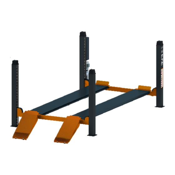
- Page 11 Installation, Operation and Parts Manual EE-6435E/EE6435E.PD PRODUCTS DESCRIPTIONS 3.1 General descriptions This four post lift is generally composed by four posts, two beams, two platforms, a hydraulic oil cylinder and a set of power unit. It is driven by an electro-hydraulic system. Up and down of platforms is controlled by the to and fro movement of the oil cylinder. It is equipped with mechanical safety locks in the four posts which automatically engage in the process of lifting so as to prevent the platforms from unexpected dropping down in case the hydraulic system fails to work.
- Page 12 Power side cross beam The opposite cross beam Ramp assembly Main control box Power unit PD assembly (optional) Turn table Side slip Portable box 3.4 Technical data EE-6435S.52L.50T.E EE-6435S.48L.50T.E Model EE-6435B.52L.50T.E EE-6435B.48L.40T.E EE-6435B.52L.50T.E.PD EE-6435B.48L.40T.E.PD Power type Electro-hydraulic Electro-hydraulic Rated capacity...
- Page 13 Installation, Operation and Parts Manual EE-6435E/EE6435E.PD 3.5 Dimensions 3.5.1 Dimension for EE-6435B.52L.50T.E.PD / EE-6435B.48L.40T.E.PD with long drive-on ramps (on-ground installation ) EE-6435B.52L.50T.E.PD EE-6435B.48L.40T.E.PD Model 5280 4880 6350 5950 5308 5808 4820 4420 1980 1580 1040...
- Page 14 Installation, Operation and Parts Manual EE-6435E/EE6435E.PD 3.5.2 Dimension for EE-6435B.52L.50T.E/ EE-6435B.48L.40T.E with long drive-on ramps (on-ground installation ) EE-6435B.52L.50T.E EE-6435B.48L.40T.E Model 5280 4880 6350 5950 5308 5808 4820 4420 1980 1580 1040...
- Page 15 Installation, Operation and Parts Manual EE-6435E/EE6435E.PD 3.5.3 Dimension for EE-6435S.52L.50T.E/ EE-6435S.48L.40T.E with long drive-on ramps (on-ground installation ) EE-6435S.52L.50T.E EE-6435S.48L.40T.E Model 5280 4880 6350 5950 5308 5808 4820 4420 3.6 Nameplate The nameplate is fixed beneath the oil tank Check the work voltage and the lift capacity printed on the name plate.
- Page 16 Installation, Operation and Parts Manual EE-6435E/EE6435E.PD INSTALLATION INSTRUCTIONS 4.1 Preparations before installation 4.1.1 Space requirements. Refer to 3.5 for the dimensions of the lift. There must also be a clearance of at least 1 meter between the lifting platform and fixed elements (e.g.
- Page 17 Installation, Operation and Parts Manual EE-6435E/EE6435E.PD 4.1.4 Tools and equipment needed for installation Tool name Specification Quantity Electrical drill With D16 and D18 drill bit. Open spanner D17-19mm Hex socket spanner D3,D4,D5mm Adjustable spanner small than D30mm Cross socket screw driver Levelling device Hammer 10 pounds...
- Page 18 Installation, Operation and Parts Manual EE-6435E/EE6435E.PD Name Note M10*35 hex head full swivel screw M10 hex nut Ф10 class C flat washer φ10 spring washer anti-vibration pad Expansion bolt M16*120 Manual 4.2 Installation attentions 4.2.1 Joints of oil hose and wiring must be firmly connected in order to avoid leakage of oil hose and looseness of electrical wires. 4.2.2 All bolts should be firmly screwed up.
- Page 19 Installation, Operation and Parts Manual EE-6435E/EE6435E.PD Step 2: Remove the packing materials. 1. Place some wooden battens (thickness of which should be more than 80mm) on the ground (other dependable devices may also applicable) and then use forklift to have the packing rack removed on to the battens so as to make its base is of some clearance from the ground. 2.
- Page 20 Installation, Operation and Parts Manual EE-6435E/EE6435E.PD Step 4: Connect the platforms and beams Firstly, connect the main beam (the beam which connects to the power side post)with two platforms. Align accurately the screw sockets on the platform and the beam and fasten them (Installers can adjust the distance between two platforms on basis of practical needs.) (Meanwhile , pull out oil hose and air hose from the power side platform and make them go through the¢40 hole reserved on the cross beam .
- Page 21 Installation, Operation and Parts Manual EE-6435E/EE6435E.PD 3. Pull out the steel cables from both ends of the cross beam and fasten them on the top plate of post (please see the Annex for the steel cable connection) Post Cross beam Steel cable M20 hex nut φ20 flat washer...
- Page 22 Installation, Operation and Parts Manual EE-6435E/EE6435E.PD Step 8: Fit on four post cap on top of the four posts. Post cap Step 9: Connect the electrical and hydraulic system. Refer to electrical and hydraulic connection diagrams before making connection. Attention: electrical system connection must be done by licensed technicians. (For three phase power supply, if the lift doesn't raise and the motor may turn in the wrong direction, in such event, interchange wires U, V in the control cabinet).
- Page 23 Installation, Operation and Parts Manual EE-6435E/EE6435E.PD 2. Fix the power unit and control box on to the post. 3. Connect oil hoses as per Annex 2. 4. Connect electrical wires to the control box as per Annex 3. Step10: Fill with hydraulic oil (only fresh and clean oil is allowed) ONLY CLEAN AND FRESH OIL ONLY .Lift must be fully lowered before changing or adding hydraulic oil.
- Page 24 Installation, Operation and Parts Manual EE-6435E/EE6435E.PD Step 11: Levelling Attention: No vehicle on platforms when leveling. 1. Firstly, level the platforms when mechanical safety locks are disengaged. Switch on and press the UP button when the green power indicating light is on. When the steel cable has been tightened, measure if the two platforms are of the same height from the ground with a leveling pipe.
- Page 25 Installation, Operation and Parts Manual EE-6435E/EE6435E.PD 4.4. Items to be checked after installation Check items Screw torque of expansion bolts : 60-80N•m; Rising speed ≥20mm/s; Noise with rated load ≤75dB; Grounding resistance: not bigger than 4Ω; Height difference of the two platform ≤5mm; Mechanical locks are robust and synchronized when running with rated load ;...
- Page 26 Installation, Operation and Parts Manual EE-6435E/EE6435E.PD 5.2 Descriptions of control panel Control panel for lifting system with PD...
- Page 27 Installation, Operation and Parts Manual EE-6435E/EE6435E.PD Control panel for lifting system without PD...
- Page 28 Installation, Operation and Parts Manual EE-6435E/EE6435E.PD Functions Descriptions Name Function Alarm buzzer Low height warning Power switch Power on/ off Power indicator Display if electricity is connected UP button Control the rising movement Door Lock Lock the control cabinet Press this button to lower / lock the platform into the mechanical safety devices.
- Page 29 Installation, Operation and Parts Manual EE-6435E/EE6435E.PD 5.3 Flow chart for operation 5.4 Operation instructions 5.4.1 Operation instructions for the lift Turn the selection switch to the state of “LIFT”. (ONLY Applicable to lifting system with PD) The lift must be only used in a static position for lifting and lowering vehicles. Only use this lift on a surface that is stable and capable of sustaining the load.
- Page 30 Installation, Operation and Parts Manual EE-6435E/EE6435E.PD 5.4.2 Operation instructions for the optional PD system Capacity: 3000kg Turn the selection switch to PD mode. The PD is designed for powered moving the wheels of the vehicle enabling inspection of suspension and steering joints 1.
- Page 31 Installation, Operation and Parts Manual EE-6435E/EE6435E.PD 5.5 Emergency lowering in case of no power In the case the safety lock is not engaged: 1. Push the front rod of the four electromagnets under the cross beam to have the four safety blocks released from the safety rods. Front rod of electromagnet Safety block and safety ladder 2.
- Page 32 Installation, Operation and Parts Manual EE-6435E/EE6435E.PD TROUBLE SHOOTING ATTENTION: If the trouble could not be fixed by yourself, please do not hesitate to contact us for help .We will offer our service at the earliest time we can. By the way, your troubles will be judged and solved much faster if you could provide us more details or pictures of the trouble. TROUBLES CAUSE SOLUTION...
- Page 33 Installation, Operation and Parts Manual EE-6435E/EE6435E.PD MAINTENANCE Easy and low cost routine maintenance can ensure the lift work normally and safely. Following are requirements for routine maintenance. You may decide the frequency of routine maintenance by consulting your lift’s working conditions and time. THE FOLLOWING PARTS NEED TO BE LUBRICATED WITH LITHIUM GREASE.
- Page 34 Installation, Operation and Parts Manual EE-6435E/EE6435E.PD Annex 1, Steel cable connection...
- Page 35 Installation, Operation and Parts Manual EE-6435E/EE6435E.PD Annex 2, Electrical schemes and parts list Electrical schemes with PD...
- Page 36 Installation, Operation and Parts Manual EE-6435E/EE6435E.PD...
- Page 37 Installation, Operation and Parts Manual EE-6435E/EE6435E.PD...
- Page 38 Installation, Operation and Parts Manual EE-6435E/EE6435E.PD Electrical connections with PD...
- Page 39 Installation, Operation and Parts Manual EE-6435E/EE6435E.PD...
- Page 40 Installation, Operation and Parts Manual EE-6435E/EE6435E.PD Electrical parts list for lifting system with PD Pos. CODE Name 320102023 Transformer(DUAL 400-230V) 320101081 Transformer (400V) SQ1;SQ2 320301009 Limit switch SQ3-SQ6 320301011 Limit switch SQ7;SQ8 320302002 Proximity switch 320303020 Selection switch 320304001 Power switch 320401014 Button 320401022...
- Page 41 Installation, Operation and Parts Manual EE-6435E/EE6435E.PD Electrical schemes without PD...
- Page 42 Installation, Operation and Parts Manual EE-6435E/EE6435E.PD...
- Page 43 Installation, Operation and Parts Manual EE-6435E/EE6435E.PD Electrical connections without PD...
- Page 44 Installation, Operation and Parts Manual EE-6435E/EE6435E.PD...
- Page 45 Installation, Operation and Parts Manual EE-6435E/EE6435E.PD Electrical parts list for lifting system without PD POS. CODE Name 320101075 Transformer(400V) 320102020 Transformer(400-230V) Motor 3.0kW SQ1;SQ2 320301009 Limit switch 8104 SQ3-SQ6 320301011 Limit switch 8108 320304001 Power switch 320401014 Button Button 320401022 Button 320101041 Button...
- Page 46 Installation, Operation and Parts Manual EE-6435E/EE6435E.PD Annex 3, Hydraulic schemes and parts list Hydraulic scheme with PD 1.oil tank 2.oil sucking filter 3.gear pump 4.coupling 5.motor 6.composite hydraulic block 7.cushion valve 8.over flow valve 9.single way valve 10.solenoid unloading valve 11.pressure supplement valve 12.tank cover 13.throttle valve...
- Page 47 Installation, Operation and Parts Manual EE-6435E/EE6435E.PD Hydraulic connections with PD Pos. CODE Name Specification Remark 610032452 Hydraulic power unit 400V-3.0KW -3PH-50HZ 624001190 Rubber oil hose L=5800mm 57L/52L/48L 624002031 Oil back hose for PD L=5800mm 57L/52L/48L Oil drain hose for cylinder of the lift D=8, L=4600mm 123010201 Oil drain hose for cylinder of the lift...
- Page 48 Installation, Operation and Parts Manual EE-6435E/EE6435E.PD Pos. CODE Name Specification Remark applicable when 624001189 Rubber oil hose L=400mm change PD position L=800mm,both straight applicable when 624001196 Rubber oil hose connectors (optional) change PD position Exploded power unit (with PD) Pos. CODE Name Specification...
- Page 49 Installation, Operation and Parts Manual EE-6435E/EE6435E.PD Pos. CODE Name Specification 330101057 SVLE.PD-J hydraulic block SVLE.PD-J 330308015 Oil supplementing valve BCYF-C-13.5 330201015 Gear pump (for 3P motor) CBK-F233-G 330308006 Solenoid unloading valve DHF06-220H/DC24 330308008 Leveling valve DHF06-228H/DC24 330302001 Single way valve DYF-C 330304001 Over flow valve...
- Page 50 Installation, Operation and Parts Manual EE-6435E/EE6435E.PD Hydraulic connections without PD POS. CODE Name Spec. Remark Power unit 3.0kW NO PD 624001194 Rubber oil hose L=6300mm 624001195 Rubber oil hose L=5700mm 624001254 Rubber oil hose L=5300mm Oil drain hose for cylinder of the lift L=4600mm 123010201 Oil drain hose for cylinder of the lift...
- Page 51 Installation, Operation and Parts Manual EE-6435E/EE6435E.PD Exploded power unit without PD POS. CODE Name Spec. 330305002 Throttle valve 330405012 Oil tank 320204017 Motor 400V/3.0KW-3PH-50HZ-2P 410010091 Reinforced plate for oil tank 6254A-A5-B12 330101063B Hydraulic block YF-2D 330201007 Gear pump (3Ph,3.0kW) CBK-F233...
- Page 52 Installation, Operation and Parts Manual EE-6435E/EE6435E.PD POS. CODE Name Spec. 330308006 Solenoid unloading valve DHF06-220H/DC24 330302001 Single way valve DYF-C 330304001 Over flow valve EYF-C 310101028 Shifting connector G1/4M14x1.5 330301001 Cushion valve HZYF-C1 207103019 Composite washer 210101003 Hex socket fitting M14X1.5 201103001 Hex flange screw...
- Page 53 Installation, Operation and Parts Manual EE-6435E/EE6435E.PD Annex 4, Mechanical exploded drawings and parts list...
- Page 54 Installation, Operation and Parts Manual EE-6435E/EE6435E.PD POS. CODE Name NOTE 614027237D Power side post 614027238C Post 612027009 Safety ladder 420270200 Post cap 614027250 Tank chain fixer A 410273993 Oil hose cover 410274353 PD charger holder for model with PD 321201006 LED torch for model with PD 203101003...
- Page 55 Installation, Operation and Parts Manual EE-6435E/EE6435E.PD POS. CODE Name NOTE 614027240D Power side crossbeam 614027241D The secondary crossbeam 410274120 Pulley A 205101070 Bushing 40*50*40 612027002 Safety block A1 420270020 Sliding block (side) 420270050 Spacer A 420270060 Spacer B 410273431B Pulley shaft A 208106001 Straight pressed cup M8*1...
- Page 56 Installation, Operation and Parts Manual EE-6435E/EE6435E.PD POS. CODE Name NOTE 612027003 Adjustable rod B 410270031B Small sheave 410270630 Spring 410270051D Safety block B1 410270061 Adjustable rod A 410270660 Spring 330310007 Electromagnet 410270601 Adjustable column 410270151 Adjustable chip 410270011 Slider holder 420270010 Slider 612027004...
- Page 57 Installation, Operation and Parts Manual EE-6435E/EE6435E.PD POS. CODE Name NOTE 202111005 Hex socket flat head screw M8*15 203101007 Hex nut 202109087 Hex socket cylinder head screw (10.9) M12*70...
- Page 58 Installation, Operation and Parts Manual EE-6435E/EE6435E.PD Pos. CODE Name NOTE 614027246D Platform A 57L.50T 614027256D Platform A 52L.50T 614027316B Platform A 48L.40T 614027247D Platform B 57L.50T 614027257D Platform B 52L.50T 614027317B Platform B 48L.40T 410273801B Pulley shaft B 410273811B Pulley shaft C 410274133 Pulley B 205101069B...
- Page 59 Installation, Operation and Parts Manual EE-6435E/EE6435E.PD Pos. CODE Name NOTE 614027248 Side slip plate 614027258 Side slip plate 614027318 Side slip plate 410250221B Bolt 420210030 Nylon sheath 410250011 Washer 206201007 Cotter pin 420270100B Ball holder 420270110B Rotor ball 410274470C Pull spring 202109020 Hex socket cylinder head screw M8*15 M8*15...
Need help?
Do you have a question about the EE-6435S and is the answer not in the manual?
Questions and answers