Table of Contents
Advertisement
Quick Links
Advertisement
Table of Contents

Subscribe to Our Youtube Channel
Related Manuals for EAE EE-6435BWF


Summary of Contents for EAE EE-6435BWF
- Page 1 EE-6435BWF Installation, Operation Four Post Lift and Parts Manual Electrical Release With auxiliary lift for wheel free service Lifting capacity: 4000KG/5000KG Distributed by Please read this entire manual carefully and completely before installation or operation of the lift. 15/06/2022...
-
Page 2: Important Notes
Liability The liability of EAE is limit to the amount that the customer has actually paid for this product. This exclusion of liability does not apply to damages caused through willful misconduct or gross negligence on the part of EAE. -
Page 3: Table Of Contents
Installation, Operation and Parts Manual EE-6435BWF IMPORTANT NOTES ................................2 SAFETY NOTES ..................................4 1.1 Operation of lifting platforms ............................... 4 1.2 Checking of the lifting platforms ............................4 1.3 Important safety notices ............................... 5 1.4 Safety duties ..................................6 1.5 Potential risks and safety measures ............................ -
Page 4: Safety Notes
Installation, Operation and Parts Manual EE-6435BWF SAFETY NOTES 1.1 Operation of lifting platforms This lift is specially designed for lifting motor vehicles. Users are not allowed to use it for any other purposes. The applicable national regulations, laws and directives must be observed. -
Page 5: Important Safety Notices
Installation, Operation and Parts Manual EE-6435BWF 1.3 Important safety notices 1.3.1 Recommend for indoor use only. DO not expose the lift to rain, snow or excessive moisture. 1.3.2 Only use this lift on a surface that is stable, level and dry and not slippery, and capable of sustaining the load. Do not install the lift on any asphalt surface. -
Page 6: Safety Duties
Installation, Operation and Parts Manual EE-6435BWF 1.4 Safety duties All safety warning labels are clearly depicted on the lift to ensure that the operator is aware of and avoid the dangers of using the lift in an incorrect manner. The labels must be kept clean and they have to be replaced if detached or damaged. -
Page 7: Potential Risks And Safety Measures
Installation, Operation and Parts Manual EE-6435BWF 1.5 Potential risks and safety measures 1.5.1 RISK OF CRUSHING Safety measures: -During lift functioning, the operator must remain at the control station -The presence of persons beneath the crossbeams and/or the platforms when they are moving, or the presence of persons inside the danger zone indicated in the following figure is strictly prohibited. -
Page 8: Packing, Storage And Transportation
Installation, Operation and Parts Manual EE-6435BWF PACKING, STORAGE AND TRANSPORTATION Packing, lifting, handling, transporting operations must be performed only by experienced personnel with appropriate knowledge of the lift and after reading this manual. 2.1 The lift was dismantled into the following 2 parts for transportation... -
Page 9: Products Descriptions
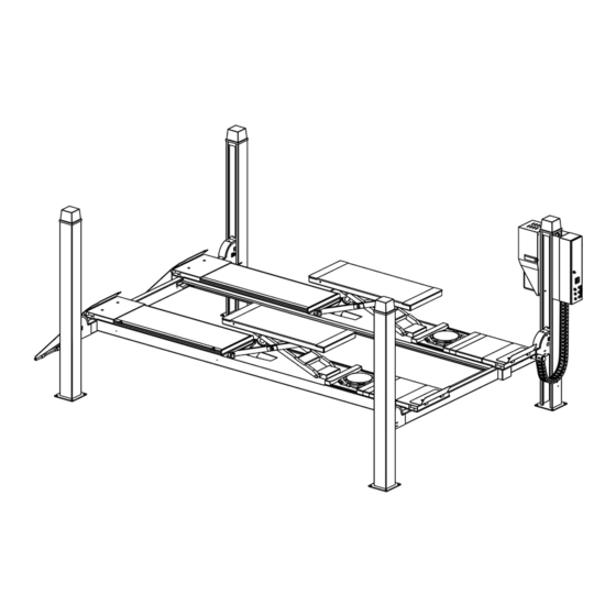
Installation, Operation and Parts Manual EE-6435BWF PRODUCTS DESCRIPTIONS 3.1 General descriptions This four post lift is generally composed by four posts, two beams, two platforms, a hydraulic oil cylinder and a set of power unit. It is driven by an electro-hydraulic system. Up and down of platforms is controlled by the to and fro movement of the oil cylinder. To ensure safety for operators, it is equipped with mechanical safety locks in the four posts , which will automatically engaged in the process of lifting so as to prevent the platforms from sudden dropping down in case the hydraulic system fails to work. -
Page 10: Dimensions
Installation, Operation and Parts Manual EE-6435BWF 3.3 Dimensions MODEL DATA 4880 (192 1/8”) 5280 (207 7/8”) 5780 (227 9/16”) 5970 (235 1/16”) 6370 (250 13/16”) 6870 (270 1/2”) 4888 (192 7/16”) 5288 (208 3/16”) 5788 (227 7/8”) 4438 (174 3/4”) 4838 (190 1/2”) -
Page 11: Safety Devices Descriptions
Installation, Operation and Parts Manual EE-6435BWF 3.4 Safety devices descriptions Safety Device Function Safety rod Ensure mechanical safety in the rising and lowering process and lock the Safety block A lifting platform at expected height. Safety block B Electromagnet Release the mechanical locking unit. -
Page 12: Technical Data
Installation, Operation and Parts Manual EE-6435BWF 3.5 Technical data Item Data Power Form Electro-hydraulic Rated capacity of the lifting platform 4000kg(48L/52L), 5000kg (48L/52L/57L) Full rise height of the main lift 1850mm Initial height of the main lift 225mm Full rise time of the main lift ≤60S... -
Page 13: Installation Instructions
Installation, Operation and Parts Manual EE-6435BWF INSTALLATION INSTRUCTIONS 4.1 Preparations before installation 4.1.1 Space requirements. Refer to 3.3 for the dimensions of the lift. There must also be a clearance of at least 0.6 meter between the lifting platform and fixed elements (e.g. - Page 14 Installation, Operation and Parts Manual EE-6435BWF Surface under the base of post: Horizontal and even (Gradients max. 0.5 %) Newly built concrete ground must be older than 20days. In mm. Platform length 4888 (192 7/16”) 5288(208 3/16”) 5788(227 7/8”)
- Page 15 Installation, Operation and Parts Manual EE-6435BWF 4.1.3 Tools and equipment needed for installation Tool name Specification Quantity Electrical driller Drill bit D18 and D20 (L=350mm) Open end spanner D17-19 Open end spanner D22—24 Adjustable wrench >D30 Hex socket spanner kits...
-
Page 16: Installation Attentions
Installation, Operation and Parts Manual EE-6435BWF Name Hex head full swivel screw M12*30 Hex socket flat head screw M12*80 Hex head full swivel screw M10*35 Hex socket button head screw M8*16 Spring washer Ø 10 Hex nut M10 Hex nut M12 Hex nut M20 Cotter pin 2.5*30... - Page 17 Installation, Operation and Parts Manual EE-6435BWF Step 2: Remove the packing materials. 1.Prepare 4 wooden battens with thickness being more than 100mm and length being more than 700mm. (other dependable devices may also applicable). Forklift the packing rack onto two of the battens so as to make its base be clear off the ground.
- Page 18 Installation, Operation and Parts Manual EE-6435BWF Pull oil hoses No.7 and No.8 from the main platform and make them go through the right side hole reserved at the crossbeam. (The hose No.7 has a right-angled fitting.) Pull hoses No.9 and NO.10 from the secondary platform and make oil hose NO.9 go through the left side hole reserved at the crossbeam.
- Page 19 Installation, Operation and Parts Manual EE-6435BWF 2. Push the power side post to the direction of the crossbeam and insert the ratchet down through the inner surface of the end plates of the crossbeam. (Take special care not to damage the limit switch NO.13 in the following fig.) 12.
- Page 20 Installation, Operation and Parts Manual EE-6435BWF Step 7: Install holders for sliding blocks, fix protective covers and fix the other end of the safety ratchets. 1. Make the holder (NO.19) for sliding block be hooked with folded edge of the post and fix it with the crossbeam using M8*12 hex socket button head screw (NO.20).
- Page 21 Installation, Operation and Parts Manual EE-6435BWF Step 9, Install the CHAIN Protection and connect electrical and hydraulic system 1. Arrange hoses and wires neatly and make them go through the CHAIN protection (NO.36) one by one. Fix one end the CHAIN onto the crossbeam and the other end onto the installation kit for control unit.
- Page 22 Installation, Operation and Parts Manual EE-6435BWF 3. Connect the electrical system. ONLY qualified electricians are permitted to do the electrical connection. Refer to electrical connection schemes in Annex 3 before making connection. Attention: For three phase power supply, if the lift doesn't raise and the motor may turn in the wrong direction, in such event, interchange wires U, V in the control cabinet.
- Page 23 Installation, Operation and Parts Manual EE-6435BWF Secondly, align the level at four corners of the runway when mechanical safety locks are engaged. Push the up button until the runway stays at a height about 800mm over the floor. Push the LOCK button to park the runway.
- Page 24 Installation, Operation and Parts Manual EE-6435BWF Step 14: Secure the post with by anchoring bolts. Screw torque: 80Nm. Before anchoring, it is necessary to check again the position for each post properly by referring to the dimension scheme as well as the corresponding installation requirements.
- Page 25 Installation, Operation and Parts Manual EE-6435BWF 3. Mount the drive-on ramp (NO.53) onto the rear end of each lifting platform using pin shafts (NO.54) and cotter pins (NO.55). 53.drive-on ramp 54.pin shaft 55. cotter pin Step 17: Level the wheel free lift 1.
-
Page 26: Items To Be Checked After Installation
Installation, Operation and Parts Manual EE-6435BWF 4.4. Items to be checked after installation Check items Screw torque of expansion bolts : 70-80Nm; Rising speed ≥20mm/s; Noise with rated load ≤75dB; Grounding resistance: not bigger than 4Ω; Height difference of the two platform ≤5mm;... -
Page 27: Descriptions Of Control Panel
Installation, Operation and Parts Manual EE-6435BWF 5.2 Descriptions of control panel POS. Name Function Alarm buzzer Low height warning Power switch Power on/ off Power indicator Display if electricity is connected UP button Control the rising movement DOWN I button Control the initial lowering movement 1.1 In case the clearance between the platform and the... - Page 28 Installation, Operation and Parts Manual EE-6435BWF 5.3.1 Use the main WHEEL-SUPPORT lifting platform Turn the selection switch to “WHEEL-SUPPORT lifting platform” RAISING LOWERING Drive the vehicle onto the runway and Release the safety locking mechanism make sure that it is properly stopped by the hand brake.
-
Page 29: Emergent Lowering In Case Of No Power Supply
Installation, Operation and Parts Manual EE-6435BWF 5.4 Emergent lowering in case of no power supply Prepare a manually operated pump with its hose being attached with M14*1.5 straight fitting (No.61). Prepare four bolts dimensioned M6*40 1. Disassemble the motor housing. -
Page 30: Trouble Shooting
Installation, Operation and Parts Manual EE-6435BWF TROUBLE SHOOTING ATTENTION: If the trouble could not be fixed by yourself, please do not hesitate to contact us for help. We will offer our solutions at the earliest time we can. Troubles could be judged and solved much faster when more details or pictures could be provided. -
Page 31: Maintenance
Installation, Operation and Parts Manual EE-6435BWF MAINTENANCE Easy and low cost routine maintenance can ensure the lift work normally and safely. Following are requirements for routine maintenance. Follow the below routine maintenance schedule with reference to the actual working condition and frequency of your lift. - Page 32 Installation, Operation and Parts Manual EE-6435BWF Components Methods Period Remove the motor housing. Hydraulic valves Every 3 months Inspect if any valve leaks. Clean or change the valve if it leaks. Open the control box to inspect all wire terminals. Screw firm if...
-
Page 33: Annex 1, Steel Cable Connection
Installation, Operation and Parts Manual EE-6435BWF Annex 1, Steel cable connection... -
Page 34: Annex 2, Electrical Schemes And Parts List
Installation, Operation and Parts Manual EE-6435BWF Annex 2, Electrical schemes and parts list... - Page 35 Installation, Operation and Parts Manual EE-6435BWF...
- Page 36 Installation, Operation and Parts Manual EE-6435BWF...
- Page 37 Installation, Operation and Parts Manual EE-6435BWF...
- Page 38 Installation, Operation and Parts Manual EE-6435BWF Printed CODE marked at Terminal Color Route Description Code wire terminals 21.20.0 (two NO.0 wires From main control box to the transmission box 5.6.7 BLUE share one (for four electromagnets) terminal) From main control box to the transmission box GREEN (for four limit switches of the "out of level protection...
- Page 39 Installation, Operation and Parts Manual EE-6435BWF Printed CODE marked at Terminal Color Route Description Code wire terminals From transmission box to the limit switch 36.37 GREEN of the "out of level protection system" in the post From transmission box to the limit switch 38.39...
-
Page 40: Annex 3, Hydraulic Schemes And Parts List
Installation, Operation and Parts Manual EE-6435BWF POS. CODE Description 320801001 Circuit breaker (3Ph) 320802001 Circuit breaker (1Ph) 320803014 Circuit breaker (4A) 320803007 Circuit breaker(16A) 320901001 AC contactor (2.2kW) 320901011 AC contactor (3.5kW) 321001004 Capacitor 321002001 Bridge rectifier 321201001 Power indicator... - Page 41 Installation, Operation and Parts Manual EE-6435BWF Seal Rings Cylinder Seal ring Seal ring code Seal ring specification Category Code description Type Y seal ring 207102008 B7-80*65*9 Type Y seal ring 207102019 B7-80*70*6 Guiding ring 207106024 80*76*10 Cylinder of the main...
- Page 42 Installation, Operation and Parts Manual EE-6435BWF Pos. CODE Description Specification REMARK Oil hose 624001867 L=6150 Oil hose 624001242 L=6650 PU hose L=4250 PU hose L=4650 PU hose L=5500 624001942 Rubber oil hose L=6850 48L/52L/57L 330503014 T shape three way hydraulic block...
- Page 43 Installation, Operation and Parts Manual EE-6435BWF Pos. CODE Description Specification 201103001 Hex flange screw M5*25 202109064 Hex socket cylinder head screw M6*30 207103019 Composite seal ring 310101003 Straight connector M14X1.5-G1/4/60 310102013 90 degree connector with swivel 08N-M14S 330101079 Composite hydraulic block...
-
Page 44: Annex 4,Exploded Drawings And Parts List
Installation, Operation and Parts Manual EE-6435BWF Pos. CODE Description Specification 320203005 400V/3.5KW -3PH-50HZ-2P Motor 320201011 220V-2.2KW-1PH-60HZ-2P Motor 330201010 Gear pump (2.2kW motor ) CBK-F225-H 330201012 Gear pump (3.5kW motor ) CBK-F242-H 330401005 Oil sucking tube XYGN-L293 NOTE: The motor is different for differnent voltage or capacity. - Page 45 Installation, Operation and Parts Manual EE-6435BWF Pos. Description NOTE Portable box II-199 Portable box III-89 48L/52L/57L Turntable(optional) Auxiliary lifting platform (main) Auxiliary lifting platform (secondary) Drive-on ramp Control unit Power unit Plastic chain 5T oil cylinder Steel rope connection block...
- Page 46 Installation, Operation and Parts Manual EE-6435BWF Pos. CODE Description Specification 614027703 Main post 6435B-A1-B3 614027091B Secondary post 6435B-A1-B1 612027001B Safety rod 6435B-A1-B2 420270090 Post cap 6435B-A11 614027108 Control unit holder 6435B-A1-B4--V2 Control unit Power unit 420250050B Round hose protector 6604B-A17...
- Page 47 Installation, Operation and Parts Manual EE-6435BWF Pos. CODE Description Specification 614027613 Main crossbeam 6435B-A2-B1-48LB--V2 614027614 Secondary crossbeam 6435B-A2-B2-48LB--V2 410274120C Pulley A 410274120 205101070 Lubrication bearing 40*50*40 612027002 Safety block A 6435B-A3-B6 420270020 Side slider block 6435B-A2-B4 420270050 Spacer A 6435B-A3-B1...
- Page 48 Installation, Operation and Parts Manual EE-6435BWF Pos. CODE Description Specification 410270660 Spring 6435B-A3-B32 330310007 Electromagnet (MQB3-10-20/AC24V) 410270601 Adjustable post 6435B-A3-B33 410270151 Adjustable chip 6435B-A3-B34 410270011 Slider holder 6435B-A2-B2 420270010 Slider 6435B-A2-B3 612027004 Safety block A2 6435B-A3-B16 410270121D Safety block B2...
- Page 49 Installation, Operation and Parts Manual EE-6435BWF Pos. CODE Description Specification 614901382 Master platform-4T48L 6435BWFV2-A4-B8-48L 614901383 Slave platform-4T48L 6435BWFV2-A4-B9-48L 614901386 Master platform-4T52L 6435BWFV2-A4-B8-52L 614901387 Slave platform-4T52L 6435BWFV2-A4-B9-52L 614901384 Master platform-5T48L 6435BWFV2-A5-B8-48L 614901385 Slave platform-5T48L 6435BWFV2-A5-B9-48L 614901388 Master platform-5T52L 6435BWFV2-A5-B8-52L 614901389 Slave platform-5T52L...
- Page 50 Installation, Operation and Parts Manual EE-6435BWF Pos. CODE Description Specification 202110004 Hex socket button head screw M8X12-GB70_2 208106001 Straight pressed oil cup M8X1-JB9740_1 202109060 Hex socket button head screw M12X145-GB70_1 615027005 Cylinder of the main wheel-support platform 5T-6435B-A3-B19 614027033B Steel rope connection block...
- Page 51 Installation, Operation and Parts Manual EE-6435BWF Pos. CODE Description Specification 202109026 Hex socket cylinder head screw M6X60-GB70_1 614901392 Slip plate 6435BWF-A4-B10-48L 614901393 Slip plate 6435BWF-A4-B10-52L 614901394 Slip plate 6435BWF-A5-B10-57L 201102015 Hex head full swivel screw M8X40-GB5783 420270020 Side block 6435B-A3-B21...
- Page 52 Installation, Operation and Parts Manual EE-6435BWF...
- Page 53 Installation, Operation and Parts Manual EE-6435BWF...
- Page 54 Installation, Operation and Parts Manual EE-6435BWF Pos. CODE Description Specification 614027268B Outer connection rod A of the wheel free lift 6435BWF-C03 614027269B Outer connection rod B of the wheel free lift 6435BWF-C04 614027270B Inner connection rod A of the wheel free lift...
- Page 55 Installation, Operation and Parts Manual EE-6435BWF Pos. CODE Description Specification 614027586C Drive-on ramp 6435BWF-C18 410270201 Roller wheel shaft 6435B-A8-B3 420270250 Small roller wheel MR30-A22-B5 410270191 Shaft 6435B-A8-B2 206201001 Cotter pin φ2.5×30 204301004 Circlip φ15...
Need help?
Do you have a question about the EE-6435BWF and is the answer not in the manual?
Questions and answers