Table of Contents
Advertisement
Quick Links
Arduino® Portenta Hat Carrier
Product Reference Manual
SKU: ASX00049
Description
The Portenta Hat Carrier is an innovative solution enabling multiple robotics, industrial, and building automation
projects. Combined with the Portenta X8, H7, or C33 boards, it evolves into a powerful industrial platform, further
complemented by its compatibility with Raspberry Pi® Hats. The carrier grants easy access to an array of
peripherals, such as CAN, Ethernet, microSD, USB, camera, and analog input and output ports. Its design is further
enhanced with dedicated pins for efficient debugging and PWM fan connector.
Target Areas:
Industrial automation, building automation, robotics, prototyping
Latest information:
The most recent datasheet version of this product is always available at:
https://docs.arduino.cc/resources/datasheets/ASX00049-datasheet.pdf
1 / 34
Arduino® Portenta Hat Carrier
Modified: 25/10/2023
Advertisement
Table of Contents

Related Manuals for Arduino ASX00049


Summary of Contents for Arduino ASX00049
- Page 1 Arduino® Portenta Hat Carrier Product Reference Manual SKU: ASX00049 Description The Portenta Hat Carrier is an innovative solution enabling multiple robotics, industrial, and building automation projects. Combined with the Portenta X8, H7, or C33 boards, it evolves into a powerful industrial platform, further complemented by its compatibility with Raspberry Pi®...
-
Page 2: Table Of Contents
Arduino® Portenta Hat Carrier CONTENTS 1 Application Examples 2 Accessories (Not Included) 3 Related Products 4 Solution Overview 5 Features 5.1 General Specifications Overview 5.2 Communication Interfaces 5.3 Other Features 6 Ratings 6.1 Recommended Operating Conditions 7 Functional Overview 7.1 Pinout 7.2 Full Pinout Table... - Page 3 7.5.12 Flashing Push Button (PB1) 8 Device Operation 8.1 Getting Started - IDE 8.2 Getting Started - Arduino Web Editor 8.3 Getting Started - Arduino IoT Cloud 8.4 Getting Started - Portenta Hat Carrier with Portenta X8 - Linux 8.5 Online Resources 8.6 Board Recovery...
-
Page 4: Application Examples
Arduino® Portenta Hat Carrier 1 Application Examples The Portenta Hat Carrier is designed to complement the Portenta family. It provides direct access to the Portentas' peripheral interfaces, enabling connections to USB and MIPI cameras. Furthermore, it improves the prototyping potential through straightforward compatibility with a broad spectrum of Raspberry Pi® Hats. -
Page 5: Related Products
Arduino Portenta X8 (SKU: ABX00049) Arduino Portenta H7 (SKU: ABX00042) Arduino Portenta H7 Lite (SKU: ABX00045) Arduino Portenta H7 Lite Connected (SKU: ABX00046) Arduino Portenta C33 (SKU: ABX00074) 4 Solution Overview The Portenta Hat Carrier works alongside the Portenta family boards. The connection between the Portenta Hat Carrier and the Portenta family boards is fast and easy thanks to the High-Density connectors (J1 and J2) found in the Portenta Hat Carrier. -
Page 6: Features
Arduino® Portenta Hat Carrier 5 Features 5.1 General Specifications Overview Characteristics Details From the onboard screw terminal block (J9): +7-32 VDC to power both the carrier and the connected Portenta family board +5 VDC power supply Supply voltage +5 VDC from the USB-C® connector of the connected Portenta family board... -
Page 7: Other Features
Arduino® Portenta Hat Carrier 5.3 Other Features Feature Description Additional onboard storage MicroSD card slot for data logging and media purposes (J7) (x1) USB USB-A 2.0 connector for data logging and external peripherals (J4) (x1) Video support Only with the Portenta X8 board through its onboard USB-C®... -
Page 8: Ratings
Arduino® Portenta Hat Carrier 6 Ratings 6.1 Recommended Operating Conditions Table 4 provides a comprehensive guideline for the optimal use of the Portenta Hat Carrier, outlining typical operating conditions and design limits. Parameter Symbol Unit 32.0 VIN from onboard screw terminal... -
Page 9: Functional Overview
Arduino® Portenta Hat Carrier 7 Functional Overview 7.1 Pinout The Portent Hat Carrier pinout is shown in Figure 2. Figure 2. Portenta Hat Carrier pinout 9 / 34 Arduino® Portenta Hat Carrier Modified: 25/10/2023... -
Page 10: Full Pinout Table
Arduino® Portenta Hat Carrier 7.2 Full Pinout Table The full pinout of the Portenta Hat Carrier is available in the following tables sorted by element/connector. 7.2.1 Raspberry Pi® 40-Pins Connector (J5) Portenta HD Silkscreen Power Net High-Density Pin Interface number... -
Page 11: 16-Pin Header (J6)
Arduino® Portenta Hat Carrier Portenta HD Silkscreen Power Net High-Density Pin Interface number Standard Pin PWM3 PWM_3 J2-65 SERIAL1_TX J1-33 UART 1 TX PWM4 PWM_4 J2-67 J1-22, J1-31, J1-42, J1-47, J1-54, J2- 24, J2-33, J2-44, J2-57, J2-70 I2S WS I2S_WS... -
Page 12: Power Block Can Bus (J9)
Arduino® Portenta Hat Carrier 7.2.3 Power Block CAN Bus (J9) Portenta HD Silkscreen Power Net High-Density Pin Interface number Standard Pin VIN 7- INPUT_7V- 32VDC J1-22, J1-31, J1-42, J1-47, J1-54, J2-24, J2-33, J2-44, J2-57, J2-70 J1-22, J1-31, J1-42, J1-47, J1-54, J2-24,... -
Page 13: Jtag Header (J3)
Arduino® Portenta Hat Carrier 7.2.5 JTAG Header (J3) Portenta HD Silkscreen Power Net High-Density Pin Interface number Standard Pin +3V3_PORTENTA J2-23, J2-34, J2-43, J2-69 JTAG_SWD J1-75 JTAG SWD J1-22, J1-31, J1-42, J1-47, J1-54, J2- 24, J2-33, J2-44, J2-57, J2-70 JTAG_SCK... -
Page 14: Usb-A (J4)
Arduino® Portenta Hat Carrier 7.2.7 USB-A (J4) Power Portenta HD Silkscreen High-Density Pin Interface number Standard Pin VIN / USB0_VBUS J1-21, J1-24, J1-32, J1-41, J1-48 USB0_D_N J1-28 USB D- USB0_D_P J1-26 USB D+ J1-22, J1-31, J1-42, J1-47, J1-54, J2-24, J2-... -
Page 15: Microsd Card Slot (J7)
Arduino® Portenta Hat Carrier 7.2.9 MicroSD Card Slot (J7) Portenta HD Silkscreen Power Net High-Density Pin Interface number Standard Pin SDC_D2 J1-63 SDC_D3 J1-65 SDC_CMD J1-57 VDD_SDCARD J1-72 SDC_CLK J1-55 J1-22, J1-31, J1-42, J1-47, J1-54, J2-24, J2-33, J2-44, J2-57, J2-70... -
Page 16: Block Diagram
Arduino® Portenta Hat Carrier 7.3 Block Diagram An overview of the Portenta Hat Carrier high-level architecture is illustrated in Figure 3. Figure 3. Portenta Hat Carrier block diagram 16 / 34 Arduino® Portenta Hat Carrier Modified: 25/10/2023... -
Page 17: Power Tree
Arduino® Portenta Hat Carrier 7.4 Power Tree Figure 4 shows the power options available on the Portenta Hat Carrier and illustrates the main system power architecture. Figure 4. Portenta Hat Carrier power tree As shown in Figure 4, the Portenta Hat Carrier can be powered in multiple ways: Through the screw terminal block connector (J9): Accepting a voltage range between +7 to +32 VDC. -
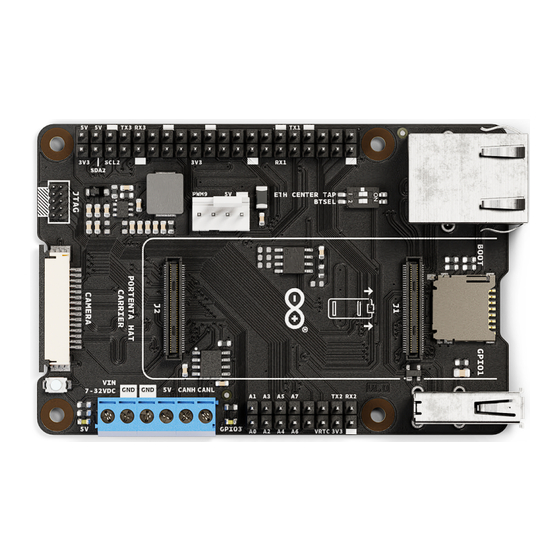
Page 18: Product Topology
Arduino® Portenta Hat Carrier 7.5 Product Topology An overview of the Portenta Hat Carrier topology is illustrated in Figure 5. Figure 5. Portenta Hat Carrier topology Item Feature Item Feature J1, J2 High-Density connectors for Portenta boards J8 RJ45 connector for Ethernet... -
Page 19: High-Density Connectors (J1-J2)
Arduino® Portenta Hat Carrier 7.5.1 High-Density Connectors (J1-J2) The High-Density connectors (J1-J2) provide connectivity with the Portenta family boards. For detailed information, refer to the Portenta Hat Carrier pinout and the respective documentation for the Portenta family boards. In Figure 6, the Portenta X8 board High-Density connectors pinout is shown as an example. -
Page 20: Jtag Connector (J3)
Arduino® Portenta Hat Carrier 7.5.2 JTAG Connector (J3) Debugging capabilities are integrated directly into the Portenta Hat Carrier and are accessible via the 10-pin JTAG connector (J3) shown in Figure 7. 7.5.3 USB-A (J4) The onboard USB-A connector (female), shown in Figure 7, is integrated in the Portenta Hat Carrier for multiple purposes, including: Connecting external peripherals such as mouse devices, keyboards, USB cameras, hubs, and hard drives. -
Page 21: 40-Pin Header Connector (J5)
Arduino® Portenta Hat Carrier 7.5.4 40-Pin Header Connector (J5) The Portenta Hat Carrier features a 40-pin header connector as shown in Figure 8, making it compatible with most of the Raspberry Pi® Hats available on the market. Figure 8. Raspberry Pi®-compatible 40-pin header connector... -
Page 22: 16-Pin Header Connector (J6)
Arduino® Portenta Hat Carrier 7.5.5 16-Pin Header Connector (J6) The Portenta Hat Carrier has a 16-pin connector as shown in Figure 9 to access multiple analog, PWM, serial ports, and power-related pins. Figure 9. 16-pin header connector The main interfaces and general-purpose pins that can be accessed via this connector are:... -
Page 23: Microsd Card Slot (J7)
Arduino® Portenta Hat Carrier 7.5.6 MicroSD Card Slot (J7) The onboard microSD card slot can be used for: Data logging operations Media purposes Figure 10. microSD card slot of the Portenta Hat Carrier 23 / 34 Arduino® Portenta Hat Carrier... -
Page 24: Rj45 Connector For Ethernet (J8)
Arduino® Portenta Hat Carrier 7.5.7 RJ45 Connector For Ethernet (J8) The RJ45 connector, directly linked to the high-density connector on the Portenta board, facilitates an Ethernet cable connection to your network. It integrates magnetics for electrical isolation, and features LED indications for activity (orange) and speed (green). -
Page 25: Screw Terminal Block (J9)
Arduino® Portenta Hat Carrier 7.5.8 Screw Terminal Block (J9) The screw terminal block connector shown in Figure 12 contains the power supply and CAN bus communication pins. Figure 12. Screw terminal block connector of the Portenta Hat Carrier Power Pins... -
Page 26: Camera Connector (J10)
Arduino® Portenta Hat Carrier 7.5.9 Camera Connector (J10) The Portenta Hat Carrier, when combined with a Portenta X8, supports MIPI cameras. The latter can be plugged into the onboard camera connector shown in Figure 13 via a flexible flat cable. -
Page 27: Pwm Header Connector (J11)
Arduino® Portenta Hat Carrier 7.5.10 PWM Header Connector (J11) The PWM header connector controls an optional fan's speed, perfect for heat dissipation in closed cases and heavy CPU-demanding applications. Figure 14. PWM connector of the Portenta Hat Carrier 7.5.11 DIP Switch Positions (SW2) The Portenta Hat Carrier has a DIP switch with two different functions depending on the Portenta family board... -
Page 28: Flashing Push Button (Pb1)
Arduino® Portenta Hat Carrier 7.5.12 Flashing Push Button (PB1) The flashing push button can serve as a general user-programmable button with a single press or can enable the board's flashing mode when pressing it longer. Figure 15. Flashing push button of the Portenta Hat Carrier To perform flashing operations:... -
Page 29: Device Operation
8.4 Getting Started - Portenta Hat Carrier with Portenta X8 - Linux The Portenta Hat Carrier with a Portenta X8 is a powerful system that runs Linux in its main core and Arduino in its secondary core. In case you want to know more about how to use Linux with your Portenta X8 and your Portenta Hat Carrier, you can check the official documentation for the Portenta Hat Carrier [4] and the Portenta X8 [5]. -
Page 30: Board Recovery
Arduino® Portenta Hat Carrier 8.6 Board Recovery Portenta C33 or Portenta H7: In case a sketch locks up the processor and the board is not reachable anymore via USB, bootloader mode can be accessed by double-tapping the reset button right after powering up. -
Page 31: Certifications
10.3 Declaration of Conformity to EU RoHS & REACH 211 01/19/2021 Arduino boards are in compliance with RoHS 2 Directive 2011/65/EU of the European Parliament and RoHS 3 Directive 2015/863/EU of the Council of 4 June 2015 on the restriction of the use of certain hazardous substances in electrical and electronic equipment. -
Page 32: Conflict Minerals Declaration
Arduino® Portenta Hat Carrier 10.4 Conflict Minerals Declaration As a global supplier of electronic and electrical components, Arduino is aware of our obligations with regard to laws and regulations regarding Conflict Minerals, specifically the Dodd-Frank Wall Street Reform and Consumer Protection Act, Section 1502. -
Page 33: Company Information
Important: The operating temperature of the EUT can’t exceed 85℃ and shouldn’t be lower than -40℃. Hereby, Arduino S.r.l. declares that this product is in compliance with essential requirements and other relevant provisions of Directive 2014/53/EU. This product is allowed to be used in all EU member states. -
Page 34: Revision History
Arduino® Portenta Hat Carrier 14 Revision History Date Revision Changes 25/10/2023 First Release 34 / 34 Arduino® Portenta Hat Carrier Modified: 25/10/2023...
Need help?
Do you have a question about the ASX00049 and is the answer not in the manual?
Questions and answers