Table of Contents
Advertisement
Quick Links
Description
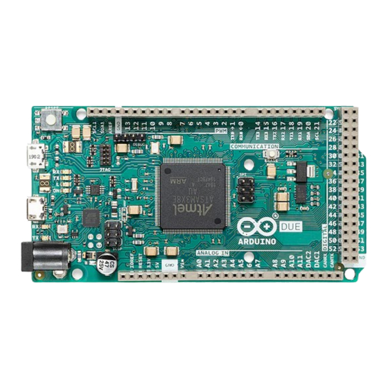
The Arduino Due is a groundbreaking microcontroller board featuring the Atmel SAM3X8E ARM Cortex-M3 CPU,
making it the first Arduino board built around a 32-bit ARM core microcontroller. With its 54x digital input/output
pins, 12x analog inputs, 4x UARTs, USB OTG capability, and 84 MHz clock, the Due offers enhanced performance
and versatility for a wide range of projects. Compatible with all Arduino shields designed for operation at 3.3 V and
compliant with the 1.0 Arduino pinout standard, the Due is a powerful tool for both beginners and experienced
makers alike.
Target Areas
Embedded Systems Development, Robotics, 3D Printing, CNC Machines, Prototyping
1 / 27
Arduino® Due
Arduino® Due
Product Reference Manual
SKU: A000062
Modified: 14/06/2024
Advertisement
Table of Contents

Related Manuals for Arduino Due


Summary of Contents for Arduino Due
- Page 1 12x analog inputs, 4x UARTs, USB OTG capability, and 84 MHz clock, the Due offers enhanced performance and versatility for a wide range of projects. Compatible with all Arduino shields designed for operation at 3.3 V and compliant with the 1.0 Arduino pinout standard, the Due is a powerful tool for both beginners and experienced makers alike.
-
Page 2: Table Of Contents
Arduino® Due Contents 1 Application Examples 2 Features 2.1 General Specifications Overview 2.2 Microcontroller 2.3 Inputs 2.4 Outputs 3 Accessories 4 Related Products 5 Rating 5.1 Recommended Operating Conditions 5.2 Power Specification 5.3 Current Consumption 6 Functional Overview 6.1 Pinout 6.2 Full Pinout Table... - Page 3 Arduino® Due 7.2 Getting Started - Arduino Web Editor 7.3 Getting Started - Arduino Cloud 7.4 Online Resources 7.5 Board Recovery 8 Mechanical Information 8.1 Board Dimensions 8.2 Board Connectors 9 Certifications 9.1 Certifications Summary 9.2 Declaration of Conformity CE DoC (EU) 9.3 Declaration of Conformity to EU RoHS &...
-
Page 4: Application Examples
Additionally, actuators such as motors or servos can be controlled by the Due to execute motion commands, allowing the robot to move and manipulate objects in its environment autonomously. -
Page 5: Features
2.1 General Specifications Overview The Arduino Due is a versatile microcontroller board designed for a wide range of applications. Powered by the Atmel SAM3X8E ARM Cortex-M3 CPU, it offers high performance and a robust set of features, making it suitable for complex projects. -
Page 6: Inputs
12x PWM outputs 3 Accessories USB Cable Type-A Male to Micro Type-B Male (Not included) 4 Related Products Arduino Mega Proto Shield Rev3 (A000080) Arduino 4 Relays Shield (A000110) Arduino Motor Shield Rev3 (A000079) 5 Rating 5.1 Recommended Operating Conditions... -
Page 7: Power Specification
Permissible range Safety Note: Unlike most traditional Arduino boards, the Arduino Due board runs at 3.3 V. Keep in mind the maximum voltage that the I/O pins can tolerate is 3.3 V. Applying voltages higher than 3.3 V to any I/O pin could damage the board. -
Page 8: Functional Overview
Arduino® Due 6 Functional Overview 6.1 Pinout The Arduino Due pinout is shown in the following figure. Arduino Due pinout Safety Note: Disconnect power before board modifications to avoid short-circuiting. 8 / 27 Arduino® Due Modified: 14/06/2024... -
Page 9: Full Pinout Table
Arduino® Due 6.2 Full Pinout Table The full pinout of the Arduino Due is available in the following tables. 6.2.1 Board's 24-Pin Header Function Type Description Not Connected IOREF IOREF Reference for digital logic voltage - connected to 3.3 V... -
Page 10: Board's 26-Pin Header
Arduino® Due 6.2.2 Board's 26-Pin Header Function Type Description D21/SCL1 Digital GPIO 21 / I2C 1 Clock D20/SDA1 Digital GPIO 20 / I2C 1 Dataline AREF Digital Analog Reference Voltage Power Ground D13/SCK Digital GPIO 13 / SPI Clock (PWM~) -
Page 11: Spi
Arduino® Due 6.2.3 SPI The board provides an SPI interface and full access to its pinout as it can be seen in the following table. Function Type Description CIPO Internal Controller In Peripheral Out Internal Power Supply of 5V Internal... -
Page 12: Digital Pins D22 - D53 Rhs
Arduino® Due 6.2.5 Digital Pins D22 - D53 RHS Function Type Description Power +5V Power Rail Digital GPIO 23 Digital GPIO 25 Digital GPIO 27 Digital GPIO 29 Digital GPIO 31 Digital GPIO 33 Digital GPIO 35 Digital GPIO 37... -
Page 13: Block Diagram
Arduino® Due 6.3 Block Diagram The block diagram with the main parts of the product can be checked in the following image: Arduino Due Block Diagram 13 / 27 Arduino® Due Modified: 14/06/2024... -
Page 14: Power Supply
Using an external voltage source connected to VIN pin, which has a recommended voltage range of 7-12 VCC. The Power Jack: The Due can be powered using a DC power supply connected to the power jack, which accepts a voltage range of 7 to 12 V. -
Page 15: Product Topology
Arduino® Due 6.5 Product Topology In the following drawing you can see the main integrated circuits and passive components of the Arduino Due board. Arduino Due Topology Ref. Description Atmel SAM3X8E ARM Cortex-M3 USB1 Native USB port USB2 Programming USB port... -
Page 16: Jtag Connector
6.5.2 Native USB Port The Arduino Due's Native USB port features a USB Type-B connector. This port allows the board to communicate directly with a computer as a USB device, enabling functionalities such as USB host/device capabilities and USB OTG (On-The-Go) functionality. -
Page 17: Programming Usb Port
Arduino Due and the computer, enabling the uploading of sketches and interaction with the Arduino IDE. The port is connected to the ATmega16U2 microcontroller, which acts as a USB-to-serial converter, simplifying the programming process. When connected to a computer, the Arduino IDE recognizes the board as a COM port, enabling seamless communication for programming and debugging purposes. -
Page 18: Board's 26-Pin Header Connector
Arduino® Due 6.5.5 Board's 26-Pin Header Connector The 26-pin header connector on the Arduino Due offers a comprehensive set of interfaces and versatile pins crucial for diverse applications These pins offer a range of functionalities, including digital input/output, serial communication, PWM (Pulse Width Modulation) outputs, and I2C (Inter-Integrated Circuit) communication. -
Page 19: Spi
Arduino® Due 6.5.6 SPI These pins facilitate communication between the Arduino Due and external SPI devices Function Type Description CIPO Internal Controller In Peripheral Out Internal Power Supply of 5 V Internal Serial Clock COPI Internal Controller Out Peripheral In... - Page 20 Arduino® Due Function Type Description Power +5V Power Rail Digital GPIO 23 Digital GPIO 25 Digital GPIO 27 Digital GPIO 29 Digital GPIO 31 Digital GPIO 33 Digital GPIO 35 Digital GPIO 37 Digital GPIO 39 Digital GPIO 41 Digital...
-
Page 21: Device Operation
If you want to program your Arduino Due while offline you need to install the Arduino® Desktop IDE [1]. To connect the Arduino Due to your computer, you will need a USB Type-B cable, which can also provide power to the board, as indicated by the LED (DL1). - Page 22 Arduino® Due 8 Mechanical Information The Arduino Due is a microcontroller board measuring 101.52 mm x 53.3 mm, featuring two USB-B connectors and a big quantity of GPIO pins headers. 8.1 Board Dimensions The Arduino Due board outline and mounting holes dimensions are shown in the figure below; all the dimensions are in mm.
- Page 23 Arduino® Due 8.2 Board Connectors Connectors of the Arduino Due are placed on the left side of the board; their placement is shown in the figure below. All the dimensions are in mm. Arduino Due Technical drawing 23 / 27 Arduino®...
- Page 24 9.3 Declaration of Conformity to EU RoHS & REACH 211 01/19/2021 Arduino boards are in compliance with RoHS 2 Directive 2011/65/EU of the European Parliament and RoHS 3 Directive 2015/863/EU of the Council of 4 June 2015 on the restriction of the use of certain hazardous substances in electrical and electronic equipment.
- Page 25 ECHA (European Chemical Agency) 1907 /2006/EC. 9.4 Conflict Minerals Declaration As a global supplier of electronic and electrical components, Arduino is aware of our obligations with regard to laws and regulations regarding Conflict Minerals, specifically the Dodd-Frank Wall Street Reform and Consumer Protection Act, Section 1502.
- Page 26 Important: The operating temperature of the EUT can’t exceed 85℃ and shouldn’t be lower than -40℃. Hereby, Arduino S.r.l. declares that this product is in compliance with essential requirements and other relevant provisions of Directive 2014/53/EU. This product is allowed to be used in all EU member states.
- Page 27 Arduino® Due 10 Revision History Date Revision Changes 12/06/2024 First release 27 / 27 Arduino® Due Modified: 14/06/2024...
Need help?
Do you have a question about the Due and is the answer not in the manual?
Questions and answers