Arduino UNO R3 A000066 - Computer Hardware Manual
- Product reference manual (13 pages)
Advertisement
Description
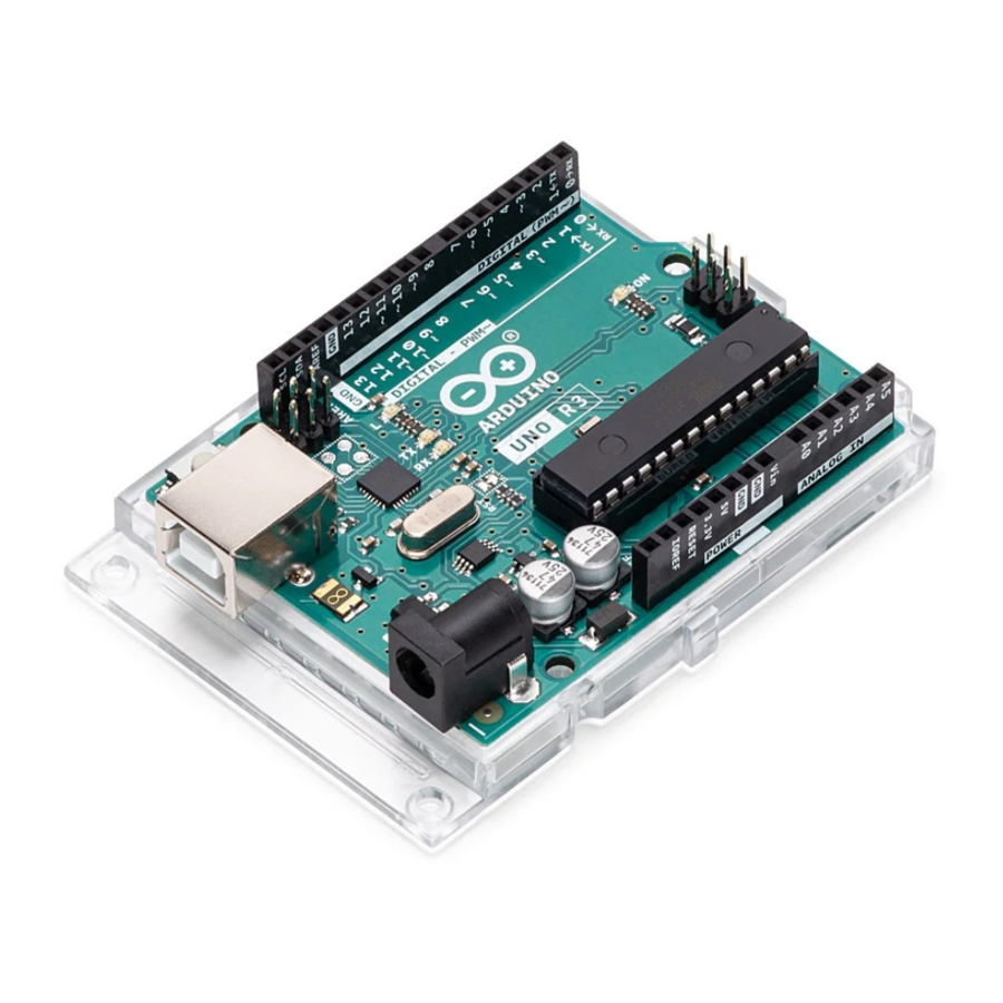
The Arduino® UNO R3 is the perfect board to get familiar with electronics and coding. This versatile development board is equipped with the well-known ATmega328P and the ATMega 16U2 Processor.
This board will give you a great first experience within the world of Arduino.
Target areas:"
Maker, introduction, industries
Features
ATMega328P Processor
- Memory
- AVR CPU at up to 16 MHz
- 32 kB Flash
- 2 kB SRAM
- 1 kB EEPROM
- Security
- Power On Reset (POR)
- Brown Out Detection (BOD)
- Peripherals
- 2x 8-bit Timer/Counter with a dedicated period register and compare channels
- 1x 16-bit Timer/Counter with a dedicated period register, input capture and compare channels
- 1x USART with fractional baud rate generator and start-of-frame detection
- 1x controller/peripheral Serial Peripheral Interface (SPI)
- 1x Dual mode controller/peripheral I2C
- 1x Analog Comparator (AC) with a scalable reference input
- Watchdog Timer with separate on-chip oscillator
- Six PWM channels
- Interrupt and wake-up on pin change
- ATMega16U2 Processor
- 8-bit AVR® RISC-based microcontroller
- Memory
- 16 kB ISP Flash
- 512B EEPROM 512B SRAM
- debugWIRE interface for on-chip debugging and programming
- Power
- 2.7-5.5 volts
The Board
Application Examples
The UNO board is the flagship product of Arduino. Regardless if you are new to the world of electronics or will use the UNO R3 as a tool for education purposes or industry-related tasks, the UNO R3 is likely to meet your needs.
First entry to electronics: If this is your first project within coding and electronics, get started with our most used and documented board; UNO. It is equipped with the well-known ATmega328P processor, 14 digital input/output pins, 6 analog inputs, USB connections, ICSP header and reset button. This board includes everything you will need for a great first experience with Arduino.
Industry-standard development board: Using the UNO R3 board in industries, there are a range of companies using the UNO R3 board as the brain for their PLC's.
Education purposes: Although the UNO R3 board has been with us for about ten years, it is still widely used for various education purposes and scientific projects. The board's high standard and top quality performance makes it a great resource to capture real time from sensors and to trigger complex laboratory equipment to mention a few examples.
Related Products
- Arduino Starter Kit
- Arduino UNO R4 Minima
- Arduino UNO R4 WiFi
- Tinkerkit Braccio Robot
Ratings
Recommended Operating Conditions
| Symbol | Description | Min | Max |
| Conservative thermal limits for the whole board: | -40°C (-40°F) | 85°C ( 185°F) |
 NOTE: In extreme temperatures, EEPROM, voltage regulator, and the crystal oscillator, might not work as expected.
Power Consumption
| Symbol | Description | Min | Typ | Max | Unit |
| VINMax | Maximum input voltage from VIN pad | 6 | - | 20 | V |
| VUSBMax | Maximum input voltage from USB connector | - | 5.5 | V | |
| PMax | Maximum Power Consumption | - | - | xx | mA |
Functional Overview
Board Topology
Top view

Board topology
| Ref. | Description | Ref. | Description |
| X1 | Power jack 2.1x5.5mm | U1 | SPX1117M3-L-5 Regulator |
| X2 | USB B Connector | U3 | ATMEGA16U2 Module |
| PC1 | EEE-1EA470WP 25V SMD Capacitor | U5 | LMV358LIST-A.9 IC |
| PC2 | EEE-1EA470WP 25V SMD Capacitor | F1 | Chip Capacitor, High Density |
| D1 | CGRA4007-G Rectifier | ICSP | Pin header connector (through hole 6) |
| J-ZU4 | ATMEGA328P Module | ICSP1 | Pin header connector (through hole 6) |
| Y1 | ECS-160-20-4X-DU Oscillator |
Processor
The Main Processor is a ATmega328P running at up to 20 MHz. Most of its pins are connected to the external headers, however some are reserved for internal communication with the USB Bridge coprocessor.
Power Tree

Power tree
Board Operation
Getting Started - IDE
If you want to program your UNO R3 while offline you need to install the Arduino Desktop IDE [1] To connect the UNO R3 to your computer, you'll need a USB-B cable. This also provides power to the board, as indicated by the LED.
Getting Started - Arduino Cloud Editor
All Arduino boards, including this one, work out-of-the-box on the Arduino Cloud Editor [2], by just installing a simple plugin.
The Arduino Cloud Editor is hosted online, therefore it will always be up-to-date with the latest features and support for all boards. Follow [3] to start coding on the browser and upload your sketches onto your board.
Sample Sketches
Sample sketches for the UNO R3 can be found either in the "Examples" menu in the Arduino IDE or in the "Documentation" section of the Arduino website [4].
Online Resources
Now that you have gone through the basics of what you can do with the board you can explore the endless possibilities it provides by checking exciting projects on Arduino Project Hub [5], the Arduino Library Reference [6] and the online Arduino store [7] where you will be able to complement your board with sensors, actuators and more.
Connector Pinouts

Pinout
JANALOG
| Pin | Function | Type | Description |
| 1 | NC | NC | Not connected |
| 2 | IOREF | IOREF | Reference for digital logic V - connected to 5V |
| 3 | Reset | Reset | Reset |
| 4 | +3V3 | Power | +3V3 Power Rail |
| 5 | +5V | Power | +5V Power Rail |
| 6 | GND | Power | Ground |
| 7 | GND | Power | Ground |
| 8 | VIN | Power | Voltage Input |
| 9 | A0 | Analog/GPIO | Analog input 0 /GPIO |
| 10 | A1 | Analog/GPIO | Analog input 1 /GPIO |
| 11 | A2 | Analog/GPIO | Analog input 2 /GPIO |
| 12 | A3 | Analog/GPIO | Analog input 3 /GPIO |
| 13 | A4/SDA | Analog input/I2C | Analog input 4/I2C Data line |
| 14 | A5/SCL | Analog input/I2C | Analog input 5/I2C Clock line |
JDIGITAL
| Pin | Function | Type | Description |
| 1 | D0 | Digital/GPIO | Digital pin 0/GPIO |
| 2 | D1 | Digital/GPIO | Digital pin 1/GPIO |
| 3 | D2 | Digital/GPIO | Digital pin 2/GPIO |
| 4 | D3 | Digital/GPIO | Digital pin 3/GPIO |
| 5 | D4 | Digital/GPIO | Digital pin 4/GPIO |
| 6 | D5 | Digital/GPIO | Digital pin 5/GPIO |
| 7 | D6 | Digital/GPIO | Digital pin 6/GPIO |
| 8 | D7 | Digital/GPIO | Digital pin 7/GPIO |
| 9 | D8 | Digital/GPIO | Digital pin 8/GPIO |
| 10 | D9 | Digital/GPIO | Digital pin 9/GPIO |
| 11 | SS | Digital | SPI Chip Select |
| 12 | MOSI | Digital | SPI1 Main Out Secondary In |
| 13 | MISO | Digital | SPI Main In Secondary Out |
| 14 | SCK | Digital | SPI serial clock output |
| 15 | GND | Power | Ground |
| 16 | AREF | Digital | Analog reference voltage |
| 17 | A4/SD4 | Digital | Analog input 4/I2C Data line (duplicated) |
| 18 | A5/SD5 | Digital | Analog input 5/I2C Clock line (duplicated) |
Mechanical Information
Board Outline & Mounting Holes

Board outline
Documents / Resources
References
Download manual
Here you can download full pdf version of manual, it may contain additional safety instructions, warranty information, FCC rules, etc.
Advertisement


Need help?
Do you have a question about the UNO R3 and is the answer not in the manual?
Questions and answers