Arduino Nano ESP32 Manual
- Product reference manual (20 pages) ,
- User manual (41 pages)
Advertisement
- 1 Description
- 2 Features
- 3 The Board
- 4 ESP32 Core
- 5 Recommended Operating Conditions
- 6 Block Diagram
- 7 Board Topology
- 8 NORA-W106-10B (Radio Module / MCU)
- 9 System
- 10 Serial Communication Protocols
- 11 External Flash Memory
- 12 USB Connector
- 13 Power Options
- 14 Pinout
- 15 Mounting Holes And Board Outline
- 16 Board Operation
- 17 Company Information
- 18 Reference Documentation
- 19 Documents / Resources
Description
The Arduino® Nano ESP32 (with and without headers) is a Nano form factor board based on the ESP32-S3
(embedded in the NORA-W106-10B from u-blox®). This is the first Arduino board to be based fully on an ESP32, and features Wi-Fi® as well as Bluetooth® LE.
The Nano ESP32 is compatible with the Arduino Cloud, and has support for MicroPython. It is an ideal board for getting started with IoT development.
Target areas:
Maker, IoT, MicroPython
Features
Xtensa® Dual-core 32-bit LX7 Microprocessor
- Up to 240 MHz
- 384 kB ROM
- 512 kB SRAM
- 16 kB SRAM in RTC (low power mode)
- DMA Controller
Power
- Operating voltage 3.3 V
- VBUS supplies 5 V via USB-C® connector
- VIN range is 6-21 V
Connectivity
- Wi-Fi®
- Bluetooth® LE
- Built-in antenna
- 2.4 GHz transmitter/receiver
- Up to 150 Mbps
Pins
- 14x digital (21x including analog)
- 8x analog (available in RTC mode)
- SPI(D11,D12,D13), I2C (A4/A5), UART(D0/D1)
Communication Ports
- SPI
- I2C
- I2S
- UART
- CAN (TWAI®)
Low Power
- 7 μA consumption in deep sleep mode*
- 240 μA consumption in light sleep mode*
- RTC Memory
- Ultra Low Power (ULP) Coprocessor
- Power Management Unit (PMU)
- ADC in RTC mode
*The power consumption ratings listed in low power modes are only for the ESP32-S3 SoC. Other components on the board (such as LEDs), consumes power as well, which increases the overall power consumption of the board.
The Board
Nano ESP32 is a 3.3 V development board based on the NORA-W106-10B from u-blox®, a module that includes a ESP32-S3 system on a chip (SoC). This module has support for Wi-Fi® and Bluetooth® Low Energy (LE), with amplified communication through a built-in antenna. The CPU (32-bit Xtensa® LX7) supports clock frequencies at up to 240 MHz.
Application Examples
Home automation: an ideal board for automating your home, and can be used for smart switches, automatic lighting and motor control for e.g. motor controlled blinds.
IoT sensors: with several dedicated ADC channels, accessible I2C/SPI buses and a robust ESP32-S3 based radio module, this board can easily be deployed to monitor sensor values.
Low power designs: create battery powered applications with low power consumption, utilising the built in low power modes of the ESP32-S3 SoC.
ESP32 Core
The Nano ESP32 uses the Arduino Board Package for ESP32 boards, a derivation of Espressif's arduino-esp32 core.
Rating
Recommended Operating Conditions
| Symbol | Description | Min | Typ | Max | Unit |
| VIN | Input voltage from VIN pad | 6 | 7.0 | 21 | V |
| VUSB | Input voltage from USB connector | 4.8 | 5.0 | 5.5 | V |
| Tambient | Ambient Temperature | -40 | 25 | 105 | °C |
Functional Overview
Block Diagram
Arduino Nano ESP32 Block Diagram

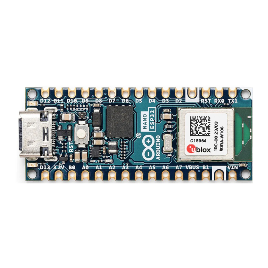
Board Topology
Front View
Top View of Arduino Nano ESP32

| Ref. | Description |
| M1 | NORA-W106-10B (ESP32-S3 SoC) |
| J1 | CX90B-16P USB-C® connector |
| JP1 | 1x15 analog header |
| JP2 | 1x15 digital header |
| U2 | MP2322GQH step down converter |
| U3 | GD25B128EWIGR 128 Mbit (16 MB) ext. flash memory |
| DL1 | RGB LED |
| DL2 | LED SCK (serial clock) |
| DL3 | LED Power (green) |
| D2 | PMEG6020AELRX Schottky Diode |
| D3 | PRTR5V0U2X,215 ESD Protection |
NORA-W106-10B (Radio Module / MCU)
The Nano ESP32 features the NORA-W106-10B stand alone radio module, embedding an ESP32-S3 series SoC as well as an embedded antenna. The ESP32-S3 is based on an Xtensa® LX7 series microprocessor.
Xtensa® Dual-Core 32bit LX7 Microprocessor
The microprocessor for the ESP32-S3 SoC inside the NORA-W106 module is a dual-core 32-bit Xtensa® LX7. Each core can run at up to 240 MHz and has 512 kB SRAM memory. The LX7 features:
- 32-bit customized instruction set
- 128-bit data bus
- 32-bit multiplier / divider
The LX7 has a 384 kB ROM (Read Only Memory), and 512 kB of SRAM (Static Random Access Memory). It also features an 8 kB RTC FAST and RTC SLOW memory. These memories are designed for low-power operations, where the SLOW memory can be accessed by the ULP (Ulta Low Power) coprocessor, retaining the data in deep sleep mode.
Wi-Fi®
The NORA-W106-10B module supports the Wi-Fi® 4 IEEE 802.11 standards b/g/n, with an output power EIRP at up to 10 dBm. The max range for this module is 500 meters.
- 802.11b: 11 Mbit/s
- 802.11g: 54 Mbit/s
- 802.11n: 72 Mbit/s max at HT-20 (20 MHz), 150 Mbit/s max at HT-40 (40 MHz)
Bluetooth®
The NORA-W106-10B module supports Bluetooth® LE v5.0 with an output power EIRP at up to 10 dBm and data rates up to 2 Mbps. It has the option to scan and advertise simultaneously, as well as supporting multiple connections in peripheral/central mode.
PSRAM
The NORA-W106-10B module includes 8 MB of embedded PSRAM. (Octal SPI)
Antenna Gain
The built-in antenna on the NORA-W106-10B module uses GFSK modulation technique, with the performance ratings listed below:
Wi-Fi®:
- Typical conducted output power: 17 dBm.
- Typical radiated output power: 20 dBm EIRP.
- Conducted sensitivity: -97 dBm.
Bluetooth® Low Energy:
- Typical conducted output power: 7 dBm.
- Typical radiated output power: 10 dBm EIRP.
- Conducted sensitivity: -98 dBm.
This data is retrieved from the uBlox NORA-W10 data sheet ( section 1.5) available here.
System
Resets
The ESP32-S3 has support for four levels of reset:
- CPU: resets CPU0/CPU1 core
- Core: resets the digital system, except for the RTC peripherals (ULP coprocessor, RTC memory).
- System: resets the entire digital system, including the RTC peripherals.
- Chip: resets the entire chip.
It is possible to conduct a software reset of this board, as well as obtaining the reset reason.
To do a hardware reset of the board, use the onboard reset button (PB1).
Timers
The Nano ESP32 has the following timers:
- 52-bit system timer with 2x 52-bit counters (16 MHz) and 3x comparators.
- 4x general-purpose 54-bit timers
- 3x watchdog timers, two in main system (MWDT0/1), one in the RTC module (RWDT).
Interrupts
All GPIOs on the Nano ESP32 can be configured to be used as interrupts, and is provided by an interrupt matrix.
Interrupt pins are configured on an application level, using the following configurations:
- LOW
- HIGH
- CHANGE FALLING
- RISING
Serial Communication Protocols
The ESP32-S3 chip provides flexibility for the various serial protocols it supports. For example, the I2C bus can be assigned to almost any available GPIO.
Inter-Integrated Circuit (I2C)
Default pins:
- A4 - SDA
- A5 - SCL
The I2C bus is by default assigned to the A4/A5 (SDA/SCL) pins for retro compatibility. This pin assignment can however be changed, due to the flexibility of the ESP32-S3 chip.
The SDA and SCL pins can be assigned to most GPIOs, however some of these pins may have other essential functions that prevents I2C operations to run successfully.
Please note: many software libraries uses the standard pin assignment (A4/A5).
Inter-IC Sound (I2S)
There two I2S controllers that are typically used for communication with audio devices. There are no specific pins assigned for I2S, this can be used by any free GPIO.
Using standard or TDM mode, the following lines are used:
- MCLK - master clock
- BCLK - bit clock
- WS - word select
- DIN/DOUT - serial data
Using PDM mode:
- CLK - PDM clock
- DIN/DOUT serial data
Read more about the I2S protocol in Espressif's Peripheral API - InterIC Sounds (I2S)
Serial Peripheral Interface (SPI)
- SCK - D13
- CIPO - D12
- COPI - D11
- CS - D10
The SPI controller is by default assigned to the pins above.
Universal Asynchronous Receiver/Transmitter (UART)
- D1 / TX
- D0 / RX
The UART controller is by default assigned to the the pins above.
Two Wire Automotive Interface (TWAI®)
The CAN/TWAI® controller is used to communicate with systems using the CAN/TWAI® protocol, particularly common in the automotive industry. There are no specific pins assigned for the CAN/TWAI® controller, any free GPIO can be used.
Please note: TWAI® is also known as the CAN2.0B, or "CAN classic". The CAN controller is NOT compatible with CAN FD frames.
External Flash Memory
Nano ESP32 features a 128 Mbit (16 MB) external flash, the GD25B128EWIGR (U3). This memory is connected to the ESP32 via Quad Serial Peripheral Interface (QSPI).
The operating frequency for this IC is 133 MHz, and has a data transfer rate at up to 664 Mbit/s.
USB Connector
The Nano ESP32 has one USB-C® port, used to power and program your board as well as sending & receiving serial communication.
Note that you should not power the board with more than 5 V via the USB-C® port.
Power Options
Power can either be supplied via the VIN pin, or via USB-C® connector. Any voltage input either via USB or VIN is stepped down to 3.3 V using the MP2322GQH (U2) converter.
The operating voltage for this board is 3.3 V. Please note that there's no 5V pin available on this board, only the VBUS can provide 5 V when the board is powered via USB.
Power Tree
Arduino Nano ESP32 power tree.

Pin Voltage
All digital & analog pins on the Nano ESP32 are 3.3 V. Do not connect any higher voltage devices to any of the pins as it will risk damaging the board.
VIN Rating
The recommended input voltage range is 6-21 V.
You should not attempt to power the board with a voltage outside the recommended range, particularly not higher than 21 V.
The efficiency of the converter depends on the input voltage via the VIN pin. See the average below for a board operation with normal current consumption:
- 4.5 V - >90%.
- 12 V - 85-90%
- 18 V - <85%
This information is extracted from the MP2322GQH's datasheet.
VBUS
There is no 5V pin available on the Nano ESP32. 5 V can only be provided via the VBUS, which is supplied directly from the USB-C® power source.
While powering the board via the VIN pin, the VBUS pin is not activated. This means you have no option of providing 5 V from the board unless powered via USB or externally.
Using the 3.3 V Pin
The 3.3 V pin is connected to the 3.3 V rail which is connected to the output of the MP2322GQH step down converter. This pin is primarily used to power external components.
Pin Current
The GPIOs on the Nano ESP32 can handle source currents up to 40 mA, and sink currents up to 28 mA. Never connect devices that draw higher current directly to a GPIO.
Mechanical Information
Pinout
Pinout for Nano ESP32.

Analog (JP1)
| Pin | Function | Type | Description |
| 1 | D13 / SCK | NC | Serial Clock |
| 2 | +3V3 | Power | +3V3 Power Rail |
| 3 | BOOT0 | Mode | Board Reset 0 |
| 4 | A0 | Analog | Analog input 0 |
| 5 | A1 | Analog | Analog input 1 |
| 6 | A2 | Analog | Analog input 2 |
| 7 | A3 | Analog | Analog input 3 |
| 8 | A4 | Analog | Analog input 4 / I²C Serial Datal (SDA) |
| 9 | A5 | Analog | Analog input 5 / I²C Serial Clock (SCL) |
| 10 | A6 | Analog | Analog input 6 |
| 11 | A7 | Analog | Analog input 7 |
| 12 | VBUS | Power | USB power (5V) |
| 13 | BOOT1 | Mode | Board Reset 1 |
| 14 | GND | Power | Ground |
| 15 | VIN | Power | Voltage Input |
Digital (JP2)
| Pin | Function | Type | Description |
| 1 | D12 / CIPO* | Digital | Controller In Peripheral Out |
| 2 | D11 / COPI* | Digital | Controller Out Peripheral In |
| 3 | D10 / CS* | Digital | Chip Select |
| 4 | D9 | Digital | Digital pin 9 |
| 5 | D8 | Digital | Digital pin 8 |
| 6 | D7 | Digital | Digital pin 7 |
| 7 | D6 | Digital | Digital pin 6 |
| 8 | D5 | Digital | Digital pin 5 |
| 9 | D4 | Digital | Digital pin 4 |
| 10 | D3 | Digital | Digital pin 3 |
| 11 | D2 | Digital | Digital pin 2 |
| 12 | GND | Power | Ground |
| 13 | RST | Internal | Reset |
| 14 | D0/RX | Digital | Digital pin 1 / Serial Receiver (RX) |
| 15 | D1/TX | Digital | Digital pin 0 / Serial Transmitter (TX) |
*CIPO/COPI/CS replaces the MISO/MOSI/SS terminology.
Mounting Holes And Board Outline

Mechanical View of Nano ESP32
Board Operation
Getting Started - IDE
If you want to program your Nano ESP32 while offline you need to install the Arduino IDE [1]. To connect the Nano ESP32 to your computer, you will need a Type-C® USB cable, which can also provide power to the board, as indicated by the LED (DL1).
Getting Started - Arduino Cloud Editor
All Arduino boards, including this one, work out-of-the-box on the Arduino Cloud Editor [2], by just installing a simple plugin.
The Arduino Cloud Editor is hosted online, therefore it will always be up-to-date with the latest features and support for all boards. Follow [3] to start coding on the browser and upload your sketches onto your board.
Getting Started - Arduino Cloud
All Arduino IoT enabled products are supported on Arduino Cloud which allows you to log, graph and analyze sensor data, trigger events, and automate your home or business.
Online Resources
Now that you have gone through the basics of what you can do with the board you can explore the endless possibilities it provides by checking exciting projects on Arduino Project Hub [4], the Arduino Library Reference [5], and the online store [6]; where you will be able to complement your board with sensors, actuators and more.
Board Recovery
All Arduino boards have a built-in bootloader which allows flashing the board via USB. In case a sketch locks up the processor and the board is not reachable anymore via USB, it is possible to enter bootloader mode by doubletapping the reset button right after the power-up.
Company Information
| Company name | Arduino S.r.l. |
| Company Address | Via Andrea Appiani, 25 Monza, MB, 20900 Italy |
Reference Documentation
| Reference | Link |
| Arduino IDE (Desktop) | https://www.arduino.cc/en/Main/Software |
| Arduino Cloud Editor | https://create.arduino.cc/editor |
| Arduino Project Hub | https://create.arduino.cc/projecthub?by=part&part_id=11332&sort=trending |
| Library Reference | https://github.com/arduino-libraries/ |
| Online Store | https://store.arduino.cc/ |
Documents / Resources
References
https://create.arduino.cc/projecthub?by=part&part_id=11332&sort=trending
![www.arduino.cc]() https://www.arduino.cc/en/Main/Software
https://www.arduino.cc/en/Main/Softwarehttps://create.arduino.cc/projecthub?by=part&part_id=11332&sort=trending
![github.com]() Arduino Libraries · GitHub
Arduino Libraries · GitHub![store.arduino.cc]() Arduino Official Store | Boards Shields Kits Accessories
Arduino Official Store | Boards Shields Kits Accessories
Download manual
Here you can download full pdf version of manual, it may contain additional safety instructions, warranty information, FCC rules, etc.
Advertisement


Need help?
Do you have a question about the Nano ESP32 and is the answer not in the manual?
Questions and answers