
Related Manuals for Classic Exhibits visionary designs VK-5124


Summary of Contents for Classic Exhibits visionary designs VK-5124
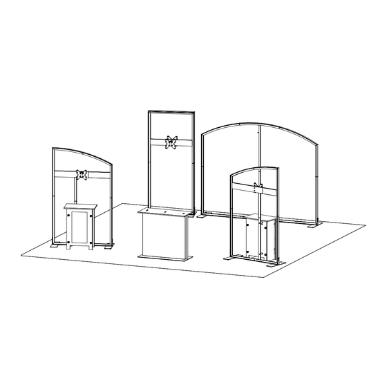
- Page 1 © 2023 Order #XXXXX VK-5124 - 20’ x 20’ Display 20’ 20’ Plan View SETUP INSTRUCTIONS If you would like to tell us about your experience with your setup instructions please email us at info@classicexhibits.com...
-
Page 2: Plan View
© 2023 Order #XXXXX Plan View = 1 sq foot... -
Page 3: General Setup Instructions
© 2023 Order #XXXXX General Information General Setup Instructions - Read entire setup instruction manual prior to WARNING unpacking parts and pieces. - The setup instructions are created specifically for this configuration. - Setup instructions are laid out sequentially in steps, including exploded views with detailed explanation for assembly. - Page 4 © 2023 Order #XXXXX CEI152 Frame Assembly Slide both connectors across seam of extrusions. Disassembly Tighten all knobs. Straight Connection 1) Loosen all knobs. Straight Connector When assembling frame, first attach all straight 2) Slide connectors off of one extrusion. connectors, then attach corner connectors.
- Page 5 © 2023 Order #XXXXX TSP49 Frame Assembly Slide connector across seam of extrusions. Disassembly Tighten all knobs. Straight Connection 1) Loosen all knobs. When assembling frame, first attach all straight Straight Connector 2) Slide connectors off of one extrusion. connectors, then attach corner connectors.
- Page 6 © 2023 Order #XXXXX SEG Installation Graphic Removal Corner A Corner B Corner D Corner C Step 1 Step 2 Step 3 It is important to first insert To remove the graphic from Insert corner A. Turn edge of Repeat Step 1 for opposite Once all corners are inserted, graphic into each alternate the frame, locate the fabric...
- Page 7 © 2023 Order #XXXXX Aero Harness Specifications Detail A Detail A Detail B Detail B Construction consists of the following materials: 1. 302/304 (1/8”) Stainless Steel Cable (Rated at 1760 lbs break strength) 2. Plated Spring-loaded Interlocking Snaps (Rated at 280 lbs working load) 3.
- Page 8 © 2023 Order #XXXXX Case Packing Top View of Each Level 11 12 Setup Hardware Graphics Level 1 Level 2 Level 3 (Bottom level) Case 1 of 7...
- Page 9 © 2023 Order #XXXXX Case Packing Top View of Each Level Graphics Setup Hardware Monitor Mounts Level 1 Level 2 Level 3 Level 4 (Bottom level) Case 2 of 7...
- Page 10 © 2023 Order #XXXXX Case Packing Top View of Each Level Graphics Setup Hardware Monitor Mount Level 1 Level 2 Level 3 Level 4 (Bottom level) Case 3 of 7...
- Page 11 © 2023 Order #XXXXX Case Packing Top View of Each Level Graphics Setup Hardware Monitor Mount Level 1 Level 2 Level 3 Level 4 (Bottom level) Case 4 of 7...
- Page 12 © 2023 Order #XXXXX Case Packing Top View of Each Level Shelf Left & SYM-407B SYM-407B Right Back Panel Front Panel Side Counter Top Shelf Panels Supports Floor Standoffs & Key Level 1 Level 2 Level 3 Level 4 Level 5 (Bottom level) Case 5 of 7...
- Page 13 © 2023 Order #XXXXX Case Packing Top View of Each Level Shelf Left & SYM-407B SYM-407B Right Back Panel Front Panel Side Counter Top Shelf Panels Supports Floor Standoffs & Key Level 1 Level 2 Level 3 Level 4 Level 5 (Bottom level) Case 6 of 7...
- Page 14 © 2023 Order #XXXXX Case Packing Top View of Each Level Setup Base Counter Hardware Level 1 Level 2 Level 3 Level 4 (Bottom level) Case 7 of 7...
- Page 15 © 2023 Order #XXXXX Aero Frame Assembly Steps: 1) Assemble Aero Frame parts labeled [1 through 24] & [25 through 48] together in numerical order, as shown. When assembled 2) Connect verticals [V] between upper & lower assemblies. 3) Apply Pillowcase Graphic to assembled frame. Using Your Setup Instructions The Aero Setup Instructions are created specifically for your configuration.
-
Page 16: Front View
© 2023 Order #XXXXX SYM-502 Frame Assembly Item Qty. Description Steps: 45”h TSP49 Vertical Extrusion Refer to the Tool-less Frame Assembly general information page. 31.305”h TSP49 Vertical Extrusion 45”h TSP49 Vertical Extrusion 1) Assemble vertical extrusions [1-2], [3-4], [11-12] & horizontals [5-6-7], [8-9-10] 31.305”h TSP49 Vertical Extrusion together, using Tool-less Spline connectors... - Page 17 © 2023 Order #XXXXX SYM-502 Frame Graphics Steps: SEG Graphic Installation 1) Apply SEG Graphics to front & back of assembled frame. Corner A Corner B When assembled Corner D Corner C S E G G ra p h ic Step 1 It is important to first insert Insert corner A.
- Page 18 © 2023 Order #XXXXX Custom Lightbox Assembly Item Qty. Description Steps: 47.5”h CEI152 Vertical Extrusion Refer to the CEI152 Frame Assembly general information page. 47.5”h CEI152 Vertical Extrusion 47.5”h CEI152 Vertical Extrusion 1) Assemble verticals [14-15], [16-17] together using straight connectors. 47.5”h CEI152 Vertical Extrusion 2) Connect vertical assemblies [14/15], [16/17] between horizontals [18,19] 42”w CEI152 Horizontal Extrusion...
- Page 19 © 2023 Order #XXXXX Custom Lightbox Attachments Steps: 1) Apply SEG graphic to front of frame assembly. Refer to the SEG Installation general information page. 2) Connect front Monitor Mount to horizontal [20]. Monitor Mount Attachment detail. 3) Apply SEG graphic to back of frame assembly. 4) Connect back Monitor Mount to horizontal [20].
- Page 20 © 2023 Order #XXXXX SYM-407 Counter Assembly Steps: Back Panel Hole Placement 1) Attach pins at bottom interior of side panels. Note: Pins are designed to be slightly angled. 2) Use screw caps to secure side panels to front & back panels. Holes on back panel of Counter are off-center to attach to backwall vertical.
- Page 21 © 2023 Order #XXXXX Left SYM-502 Frame Assembly Item Qty. Description Steps: 45”h TSP49 Vertical Extrusion Refer to the Tool-less Frame Assembly general information page. 31.305”h TSP49 Vertical Extrusion 45”h TSP49 Vertical Extrusion 1) Assemble vertical extrusions [1-2], [3-4] & horizontal 45”h TSP49 Vertical Extrusion extrusions [5-6], [7-8] together, using Tool-less Spline connectors...
- Page 22 © 2023 Order #XXXXX Left SYM-502 Frame Attachments Steps: 1) Apply SEG graphic to side of frame with counter & monitor mount first. Refer to the SEG Installation general information page. 2) Connect Monitor Mount to horizontal [11]. See Monitor Mount Attachment detail.
- Page 23 © 2023 Order #XXXXX Right SYM-502 Frame Assembly Item Qty. Description Steps: 45”h TSP49 Vertical Extrusion Refer to the Tool-less Frame Assembly general information page. 31.305”h TSP49 Vertical Extrusion 45”h TSP49 Vertical Extrusion 1) Assemble vertical extrusions [1-2], [3-4] & horizontal 45”h TSP49 Vertical Extrusion extrusions [5-6], [7-8] together, using Tool-less Spline connectors...
- Page 24 © 2023 Order #XXXXX Right SYM-502 Frame Attachments Steps: 1) Apply SEG graphic to side of frame with counter & monitor mount first. Refer to the SEG Installation general information page. 2) Connect Monitor Mount to horizontal [11]. See Monitor Mount Attachment detail.
- Page 25 © 2023 Order #XXXXX MOD-1717 Reception Counter Assembly Item Qty. Description Steps: 41.040”h CEI152 Vertical Extrusion 1) Attach U-Channel to lower horizontal [24]. See U-Channel Attachment detail. 41.040”h CEI152 Vertical Extrusion 2) Assemble verticals [22,23] between horizontals [24,25] using corner connectors. 42”w CEI152 Horizontal Extrusion Refer to the CEI152 Frame Assembly general information page.
Need help?
Do you have a question about the visionary designs VK-5124 and is the answer not in the manual?
Questions and answers