
Subscribe to Our Youtube Channel
Related Manuals for Classic Exhibits VISIONARY DESIGNS VK-5116


Summary of Contents for Classic Exhibits VISIONARY DESIGNS VK-5116
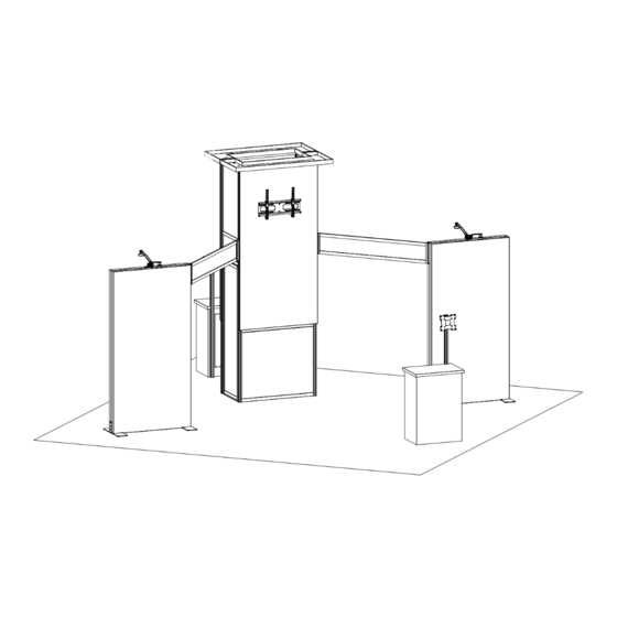
- Page 1 © 2023 Order #XXXXX VK-5116 - 20’ x 20’ Island Exhibit 20’ 20’ Plan View SETUP INSTRUCTIONS If you would like to tell us about your experience with your setup instructions please email us at info@classicexhibits.com...
-
Page 2: Plan View
© 2023 Order #XXXXX Plan View = 1 sq foot... -
Page 3: General Setup Instructions
© 2023 Order #XXXXX General Information General Setup Instructions - Read entire setup instruction manual prior to WARNING unpacking parts and pieces. - The setup instructions are created specifically for this configuration. - Setup instructions are laid out sequentially in steps, including exploded views with detailed explanation for assembly. - Page 4 © 2023 Order #XXXXX TSP46 Frame Assembly Slide connector across seam of extrusions. Disassembly Tighten all knobs. Straight Connection 1) Loosen all knobs. When assembling frame, first attach all straight Straight Connector 2) Slide connectors off of one extrusion. connectors, then attach corner connectors.
- Page 5 © 2023 Order #XXXXX CEI152 Frame Assembly Slide both connectors across seam of extrusions. Disassembly Tighten all knobs. Straight Connection 1) Loosen all knobs. Straight Connector When assembling frame, first attach all straight 2) Slide connectors off of one extrusion. connectors, then attach corner connectors.
- Page 6 © 2023 Order #XXXXX EuroLT Assembly Level 1 = Blue Panel Lock Level 2 = When Required Level 3 = Green Level 4 = Black Panel Lock With Right Hand Thumb When Required Using Your Setup Instructions Close to Seam Color Coded Clip Squeeze, Left Hand...
- Page 7 © 2023 Order #XXXXX SEG Installation Graphic Removal Corner A Corner B Corner D Corner C Step 1 Step 2 Step 3 It is important to first insert To remove the graphic from Insert corner A. Turn edge of Repeat Step 1 for opposite Once all corners are inserted, graphic into each alternate the frame, locate the fabric...
- Page 8 © 2023 Order #XXXXX Crate Packing CRATE PACKING Crate 1 of 1...
-
Page 9: Tower Assembly
© 2023 Order #XXXXX Tower Assembly Steps: 1) Assemble lower horizontals [5,6,9] & Door Threshold [11] between verticals [1,2,3,4]. See Door Threshold Attachment detail. Item Qty. Description Door Threshold 2) Connect horizontals [5A,6A] between verticals [1,2], [3,4]. 42.5”h S44 Vertical Extrusion w/ TSP3 Attachment 3) Insert Infill... - Page 10 © 2023 Order #XXXXX Tower Assembly (cont’d) Item Qty. Description Steps: 95”h TSP46 Vertical Extrusion Refer to the TSP46 Frame Assembly general information page. V4 Connector 95”h TSP46 Vertical Extrusion 48”w TSP46 Horizontal Extrusion 1) Assemble verticals [4C,5] between horizontals [6,6A] using corner connectors. Slide V4 connector into groove of 48”w TSP46 Horizontal Extrusion 2) Attach horizontal [10] between verticals [4C,5].
- Page 11 © 2023 Order #XXXXX Tower Assembly (cont’d) Item Qty. Description Steps: 60”w x 23”d x 2.5”h Ceiling Panel 1) Connect Door between verticals [1/1A] & [3/3A]. 60”w x 23”d x 2.5”h Ceiling Panel Door Attachment detail. 2) Attach Ceiling Panels [A,B] to top of tower assembly, using bolts.
- Page 12 © 2023 Order #XXXXX Side Frame Assembly Item Qty. Description Steps: 1/1A 48”w CEI152 Horizontal Extrusion Refer to the CEI152 Frame Assembly general information page. 2/2A/2B 2/1/1 95”h CEI152 Vertical Extrusion Base Plate w/ foot 1) Assemble verticals [2,2A] between horizontals [1,1A] using corner connectors. 2) Connect verticals [2,2B] between horizontals [1,1A] using corner connectors.
- Page 13 © 2023 Order #XXXXX Side Frames to Tower Connection Item Qty. Description Steps: 3/3A 12”h PR41/PR46 Hinge Connector 1) Attach connectors [3,3A] to assembled tower & frames as shown; SEG Graphic 4/4A 66”w Z41 Horizontal Extrusion PR41/PR46 Hinge Connector detail. Assemble horizontals [4,4A] 15”w PR63 Conduit between connectors [3,3A], inserting Infills.
- Page 14 © 2023 Order #XXXXX MOD-1527 Monitor Kiosks Item Qty. Description Steps: 23”w x 38”h LT Panel Refer to the LT Panel Assembly general information page. 38”h LT 90° Corner Connector When assembled 14.125”w x 38”h LT Panel 1) Assemble panels & connectors [1] through [10] in numerical order as shown. 38”h LT 90°...
Need help?
Do you have a question about the VISIONARY DESIGNS VK-5116 and is the answer not in the manual?
Questions and answers