Table of Contents
Advertisement
Advertisement
Table of Contents

Related Manuals for Atlas Copco GA 37+


Summary of Contents for Atlas Copco GA 37+
- Page 1 Instruction book Oil-injected screw compressors GA 37+, GA 45+...
- Page 3 Atlas Copco Oil-injected screw compressors GA 37+, GA 45+ Instruction book Original instructions COPYRIGHT NOTICE Any unauthorized use or copying of the contents or any part thereof is prohibited. This applies in particular to trademarks, model denominations, part numbers and drawings.
-
Page 4: Table Of Contents
Instruction book Table of contents Safety precautions......................6 Safety icons..........................6 General safety precautions....................6 Safety precautions during installation................7 Safety precautions during operation..................8 Safety precautions during maintenance or repair............10 Dismantling and disposal......................11 General description...................... 13 Introduction..........................13 Air and oil circuit........................16 Cooling system.........................19 Condensate system........................19... - Page 5 Instruction book Data menu..........................38 Service menu..........................40 Week timer menu........................42 3.10 Event history menu........................42 3.11 Machine settings menu......................43 3.12 Controller settings menu..................... 46 3.13 Access level..........................49 Energy recovery (optional)..................51 Energy recovery unit......................51 Energy recovery systems...................... 52 Operation..........................53 Maintenance..........................
- Page 6 Instruction book During operation........................76 Checking the display....................... 78 Stopping ............................80 Taking out of operation......................81 Maintenance........................82 Preventive maintenance schedule..................82 Oil specifications........................84 Drive motor ..........................86 Air filter............................86 Oil and oil filter change......................87 Coolers............................. 88 Safety valves..........................90 Dryer maintenance instructions...................90 Service kits..........................
- Page 7 Instruction book Instructions for use....................108 Guidelines for inspection...................109 Pressure equipment directives..................110 Declaration of conformity...................111 2920 7196 21...
-
Page 8: Safety Precautions
Instruction book Safety precautions Safety icons Explanation Danger to life Warning Important note General safety precautions 1. The operator must employ safe working practices and observe all related work safety requirements and regulations. 2. If any of the following statements does not comply with the applicable legislation, the stricter of the two shall apply. -
Page 9: Safety Precautions During Installation
Instruction book 6. Never play with compressed air. Do not apply the air to your skin or direct an air stream at people. Never use the air to clean dirt from your clothes. When using the air to clean equipment, do so with extreme caution and wear eye protection. 7. -
Page 10: Safety Precautions During Operation
Instruction book machines shall take adequate precautions to ensure that there is no one checking or working on the machine. To this end, a suitable notice shall be affixed to the start equipment. 11. Air-cooled machines must be installed in such a way that an adequate flow of cooling air is available and that the exhausted air does not recirculate to the compressor air inlet or cooling air inlet. - Page 11 Instruction book 3. Persons switching on remotely controlled machines shall take adequate precautions to ensure that there is no one checking or working on the machine. To this end, a suitable notice shall be affixed to the remote start equipment. 4.
-
Page 12: Safety Precautions During Maintenance Or Repair
Instruction book Safety precautions during maintenance or repair All responsibility for any damage or injury resulting from neglecting these precautions, or non observance of the normal caution and care required for installation, operation, maintenance and repair, even if not expressly stated, will be disclaimed by the manufacturer. -
Page 13: Dismantling And Disposal
Instruction book 19. Make sure that all sound-damping material and vibration dampers, e.g. damping material on the bodywork and in the air inlet and outlet systems of the compressor, is in good condition. If damaged, replace it by genuine material from the manufacturer to prevent the sound pressure level from increasing. - Page 14 Instruction book At the end of life-time of the electric and electronic equipment (EEE) it must be taken to separate collection. For more information check with your local waste authority, customer center or distributor. Disposal of other used material Used filters or any other used material (for example, filter bags, filter media, desiccant, lubricants, cleaning rags and machine parts) must be disposed of in an environmentally friendly and safe manner, and in line with the local recommendations and environmental legislation.
-
Page 15: General Description
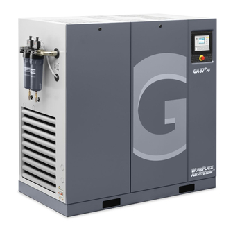
Instruction book General description Introduction GA 37 and GA 45 are single-stage, oil-injected screw compressors, driven by an electric motor. The compressors are air cooled or water cooled. ™ The compressors are controlled by an Elektronikon Touch controller. The controller is fitted to the right hand door panel on the front side. An electric cabinet comprising the motor starter is located behind this panel. - Page 16 Instruction book Figure 2: Motor side view, Pack Figure 3: Service side view, Pack 2920 7196 21...
- Page 17 Instruction book Figure 4: Motor side view, Full-Feature Figure 5: Service side view, Full-Feature Electric cabinet Outlet valve 2920 7196 21...
-
Page 18: Air And Oil Circuit
Instruction book Air cooler Oil cooler Compressor element ™ Elektronikon Touch controller Cooling fan Motor of the compressor Emergency stop button Unloader Da (Dm) Condensate outlets Air filter Air receiver (oil separator tank) Oil filter Table 1: References Air and oil circuit Air circuit Figure 6: Flow diagram, air circuit (compressors without integrated dryer) 2920 7196 21... - Page 19 Instruction book Figure 7: Flow diagram, air circuit (compressors with integrated dryer) Reference Description Intake air Air/oil mixture Wet compressed air Condensate Dried compressed air Description Air drawn through inlet filter (AF) and open inlet valve (IV) of the unloader is compressed in compressor element (E).
- Page 20 Instruction book Under all circumstances, the minimum pressure valve (Vp) keeps the pressure in the separator tank (AR) above the minimum value that is required for lubrication of the compressor element. An integrated check valve prevents the compressed air downstream the minimum pressure valve from being vented to atmosphere during unloaded operation.
-
Page 21: Cooling System
Instruction book Cooling system Diagram Reference Description Intake air Air/oil mixture Wet compressed air Condensate Description The cooling system on air-cooled compressors comprises air cooler (Ca) and oil cooler (Co). The cooling air flow is generated by fan (FN). Condensate system The condensate, collected in the moisture trap of the air cooler, is evacuated via an automatic drain. - Page 22 Instruction book • When pressed during normal operation, it starts the manual drain test. • When pressed during an alarm, it resets the control logic • By pressing the Test button for at least 5 seconds, the self diagnosis routine will start. Figure 9: Electronic condensate drains Green LED on Normal operation, drain is in standby and awaiting condensate.
- Page 23 Instruction book Red LED blinking slowly: cleaning routine 1 The drain’s tank is filled and the water cannot be drained or can only be drained very slowly. In normal operation, the drain gets 20 seconds time to drain all water. If the drain is not emptied within this time frame, a (first) cleaning routine is activated, alternatively opening and closing the valve for 2 seconds, during maximum 30 cycles.
- Page 24 Instruction book Drain connections Figure 10: Condensate drain connections Reference Designation Automatic drain connection Automatic drain connection of the dryer (only on units with integrated dryer) 2920 7196 21...
-
Page 25: Regulating System
Instruction book Regulating system Load/unload regulating system Figure 11: Regulating system (loaded condition) Loading When the net pressure is below the loading pressure, solenoid valve (Y1) is energised. Results: • The space above unloading valve/blow-off valve (UV) is connected with the oil separator tank pressure (1) via the solenoid valve. -
Page 26: Electrical System
Instruction book Electrical system Electrical components The electrical system is comprised of the following components: Figure 12: Typical example of electric cubicle Reference Designation Fuse Fuse Fuse F7/8/9 Fuses (only on units with integrated dryer) Overload relay, compressor motor Circuit breaker, fan motor (on air-cooled compressors) Auxiliary relay Auxiliary contactor (only on units with integrated dryer) Auxiliary contactor (only on units with integrated dryer) -
Page 27: Air Dryer
Instruction book Reference Designation Transformer Earth terminal Customer supply connection Electrical diagram 9820 3003 16 Service diagram The complete electrical diagram can be found in the electric cubicle and in the technical documentation, supplied with the machine. Air dryer (On compressors with integrated dryer only) Flow diagram Figure 13: Air dryer Reference... - Page 28 Instruction book Reference Name Capillary Bypass valve Condenser cooling fan Pressure switch, fan control Liquid separator Compressed air circuit Compressed air enters heat exchanger (1) and is cooled by the outgoing, cold, dried air. Water in the incoming air starts to condense. The air then flows through heat exchanger/evaporator (2), where the refrigerant evaporates, causing the air to be cooled further to close to the evaporating temperature of the refrigerant.
-
Page 29: Elektronikon™ Touch Controller
Instruction book ™ Elektronikon Touch controller Controller ™ Figure 14: The Elektronikon Touch controller Introduction The controller has the following functions: • Controlling the unit • Protecting the unit • Monitoring components subject to service • Automatic Restart After Voltage Failure (ARAVF) Automatic control of the unit The controller maintains the net pressure between programmable limits by automatically loading and unloading the unit (fixed speed units) or by adapting the motor speed (units with frequency... - Page 30 Instruction book It is possible to program a number of time-based commands for automatic start/ stop. Take into account that a start command will be executed (if programmed and activated), even after manually stopping the unit. Protecting the unit Shutdown Several sensors are provided on the unit.
-
Page 31: Control Panel
Instruction book If the function is activated and provided the regulator was in the automatic operation mode, the unit will automatically restart if the supply voltage to the module is restored. The ARAVF label shall be glued next to the controller. Control panel Figure 15: Control panel Parts and functions... -
Page 32: Icons Used
Instruction book Icons used Menu icons Menu Icon Menu Icon Menu Icon Status Inputs Outputs Data Counters Aux. Equipment Converters Parameters Overview Service Service Plan Service Service History Service functions Clean Screen Week Week Timer Remaining Running Time Event History Saved Data 2920 7196 21... - Page 33 Instruction book Menu Icon Menu Icon Menu Icon Alarms Regulation Control Parameters Machine Converter(s) Settings Aux. Equipment Parameters Internal SmartBox Auto Restart Ethernet Settings Network Settings CAN Settings Language Localisation Date/Time Controller Settings Units User Password Help Information Status icons Icon Description Motor Stopped...
- Page 34 Instruction book Running Unloaded Manual Unload Running Unloaded Wait Running Loaded Failed to Load Running Loaded Wait Manual Stop Machine Control Mode, Local Machine Control Mode, Remote Machine Control Mode, LAN Automatic Restart After Voltage Failure Week Timer Active System icons Icon Description Basic User...
- Page 35 Instruction book Antenna 100% Change between screens (indication) Energy recovery Dryer Element Drain(s) Analogue Output Menu Reset Auto Restart Filter(s) Cooler Valve(s) Power Meter Input icons Icon Description Pressure Temperature Special Protection Open 2920 7196 21...
-
Page 36: Main Screen
Instruction book Closed This chapter gives a general survey of available icons. Not all icons mentioned in this chapter are applicable to every machine. Main screen Function The Main screen is the screen that is shown automatically when the voltage is switched on. It is switched off automatically after a few minutes when there is no touch input. -
Page 37: Quick Access Screen
Instruction book Reference Designation Function This icon shows the current status of Status the unit. Indicates which page you currently see. The middle indication is the main screen, left is the menu screen and at Page indicator the right the quick access screen. Swipe left or right to go to another screen. -
Page 38: Menu Screen
Instruction book Function Description The control mode can be changed by tapping this icon. • Local control via start/stop buttons • Remote control via digital input(s) Control mode • LAN control via the network. When in Remote or LAN control, the start/stop buttons on the controller will not work. - Page 39 Instruction book Reference Designation Function The data menu contains the status of the unit, information Data about the Inputs, Outputs and Counters. The Auxiliary equipment can also be viewed through this menu. The service menu contains the Service information. The ‘Clean Service screen’...
-
Page 40: Data Menu
Instruction book This is the main menu structure. The structure can be different depending on the configuration of the unit. Data menu Function This screen is used to display the following submenus: • Status • Inputs • Outputs • Counters •... - Page 41 Instruction book This menu shows the current status of the unit. If an alarm is active, it can be viewed by tapping the alarm message. To reset an alarm, tap the reset button (1). Before remedying, consult the Safety precautions. Before resetting a warning or shutdown message, always solve the problem.
-
Page 42: Service Menu
Instruction book Stop the unit and switch off the supply before connecting external equipment. Check the Safety precautions. Counters menu Tap the Counters icon to enter the Counters menu. This menu shows an overview of all actual hours and counters of the unit and controller. Auxiliary equipment menu Tap the Aux. - Page 43 Instruction book Description Reference Designation Service Service functions (Only visible as advanced user) Clean screen Service menu Tap the Service icon to enter the Service menu. This menu shows the remaining Running Hours and the remaining Real Time Hours until the next service.
-
Page 44: Week Timer Menu
Instruction book Week timer menu Function This screen is used to set up to 4 different week timers with each up to 8 settings per day. The week timers can be activated through this screen. A Remaining Running Time can be set from 5 up to 240 minutes. Procedure To enter the Week Timer menu screen: 1. -
Page 45: Machine Settings Menu
Instruction book 1. Tap the Menu button 2. Tap the Event History icon Description Reference Designation Saved Data Saved data Tap the Saved Data icon to enter the Saved Data menu. Scroll through the items swiping up and down in this list. The event date and time is shown at the right side of the screen. - Page 46 Instruction book Procedure To enter the Machine settings menu screen: 1. Tap the Menu button 2. Tap the Machine Settings icon Description Reference Designation Alarms menu Regulation menu Control Parameters menu Aux. Equipment Parameters menu Auto Restart menu Alarms menu Tap the Alarms icon to enter the Alarms menu.
- Page 47 Instruction book Setpoints or pressure bands can be modified through this menu. Modify a setting When tapping a list item, a selection screen pops up. The user can modify the setting by tapping ‘–’ or ‘+’ and can confirm by tapping ‘V’ or decline by tapping ‘X’. Change a selection When tapping a list item, a selection screen pops up.
-
Page 48: Controller Settings Menu
Instruction book Modify a setting When tapping a list item, a selection screen pops up. The user can modify the setting by tapping ‘–’ or ‘+’ and can confirm by tapping ‘V’ or decline by tapping ‘X’. Auto restart menu If the function is activated and provided the regulator was in the automatic operation mode, the unit will automatically restart if the supply voltage to the module is restored. - Page 49 Instruction book Procedure To enter the Controller Settings menu screen: 1. Tap the Menu button 2. Tap the Controller Settings icon Description Reference Designation Network Settings menu Localisation menu User Password menu Help menu Information menu Network settings menu Tap the Network Settings icon to enter the Network Settings menu. Ethernet Settings The list of Ethernet Settings is shown.
- Page 50 Instruction book Localisation menu Tap the Localisation icon to enter the Localisation menu. Language The language setting of the controller can be modified through this menu. Date/Time The date and time settings of the controller can be modified through this menu. Units The units displayed can be modified through this menu.
-
Page 51: Access Level
Instruction book This menu can show a link to the web page of your supplier, a helpdesk phone number or other helpful information. Information menu Tap the Information icon to enter the Information menu. This menu shows information about the controller. 3.13 Access level Function... - Page 52 Instruction book Reference Designation Function Full This access level is only to be used by certified technicians. Decline Tap to decline the selected user level. Confirm Tap to confirm the selected user level. 2920 7196 21...
-
Page 53: Energy Recovery (Optional)
Instruction book Energy recovery (optional) Energy recovery unit Description A large part of the energy required for any compression process is transformed into heat. For oil- injected screw compressors, the major part of the compression heat is dissipated through the oil system. -
Page 54: Energy Recovery Systems
Instruction book Reference Designation Water inlet pipe Water outlet pipe Temperature sensor, water inlet pipe Temperature sensor, water outlet pipe Oil drain plug Oil flexible from compressor oil separator vessel to ER unit Oil flexible from ER unit to oil filter housing Pressure relief valve Location of heat exchanger by-pass valve (BV2) Heat exchanger... -
Page 55: Operation
See section Cooling water requirements. If in doubt, consult Atlas Copco. Operation Description The compressor oil flow is controlled by two thermostatic valves (BV1 and BV2), ensuring reliable compressor operation and optimal energy recovery. - Page 56 Instruction book Figure 17: Flow diagram of compressor with energy recovery system Reference Designation Reference Designation Thermostatic bypass valve of Oil filter ER unit Oil/water heat exchanger (ER Oil separator tank unit) Thermostatic bypass valve in Compressor element oil filter housing Oil cooler (compressor) Aftercooler (compressor) Water inlet...
-
Page 57: Maintenance
Instruction book Energy recovery system in use (see drawing) Compressor start-up When the compressor is started up from cold, the oil temperature will be low. Bypass valve (BV2) shuts off the oil supply through the heat exchanger (HE) and bypass valve (BV1) shuts off the oil supply through the oil cooler (Co) to prevent the compressor oil from being cooled. -
Page 58: Energy Recovery Data
Instruction book 1. Run the unit until warm. Stop the unit, switch off the isolating switch and close the air outlet valve of the compressor. 2. Depressurize the compressor and drain the oil by opening the drain valve on the oil separator vessel. - Page 59 Instruction book Minimum Nominal Maximum Temperature input setting setting setting Water inlet temperature of energy recovery ˚C Water inlet temperature of energy recovery ˚F Depends on Energy recovery water outlet temperature ˚C application Depends on Energy recovery water outlet temperature ˚F application To modify a setting, consult the relevant section in the description of the controller.
-
Page 60: Cooling Water Requirements
Instruction book Cooling water requirements General Cooling water needs to fulfill certain requirements in order to avoid problems of scaling, fouling, corrosion or bacterial growth. In open circuit cooling towers, protective measures must be taken to avoid the growth of harmful bacteria such as legionella pneumophila when there is a risk of inhalation of the water droplets. - Page 61 Instruction book Type of cooling system Materials Standard Energy recovery Containing copper 7.5 - 9.3 7.5 - 9.3 Stainless steel with Closed loop carbon steel and / or 7.5 - 9.3 7.5 - 9.3 cast iron Stainless steel only 6 - 9.3 6 - 9.3 The values in bold are rejection limits.
- Page 62 Instruction book in which • A : depends on the total solids concentration • B : depends on the water temperature at the outlet of the heat exchanger • C : depends on the calcium hardness (CaCO • D : depends on the HCO concentration or M-alkalinity The values of A, B, C and D can be found in below table: Total...
- Page 63 Instruction book 6. Chlorides (Cl Chloride ions will create pitting corrosion on stainless steel. Their concentration should be limited, depending from the RSI value. 5.6 < RSI < 6.3 < RSI < 6.9 < RSI < RSI < 5.5 7.6 < RSI (ppm) For energy recovery systems, the limit is 100 ppm.
- Page 64 Instruction book Suspended solids (ppm) Type of cooling system Standard Energy recovery Single pass < 10 < 1 Recirculating (with tower) < 10 not applicable Closed loop < 10 < 1 12. Oil or grease < 1 ppm (rejection value) 13.
-
Page 65: Installation
Instruction book Installation Dimension drawings The dimension drawing can be found in the technical documentation, supplied with the unit. Dimension drawing Model 9828 5324 39-01 GA 37 , GA 45 Pack, air-cooled, metric units 9828 5324 39-02 GA 37 , GA 45 Pack, air-cooled, imperial units 9828 5324 49-01 GA 37... - Page 66 If frost might occur, the appropriate measures must be taken to avoid damage to the machine and its ancillary equipment. Consult Atlas Copco. Moving/lifting The compressor can be moved by a lift truck using the slots in the frame. Take care not to damage the bodywork during lifting or transport.
- Page 67 Instruction book Compressor room example Reference Designation Ventilation proposals Minimum free area to be reserved for the compressor installation Table 3: Text on drawing All piping to be connected stress-free to the compressor. Installation guidelines 1. Install the compressor unit on a solid, level floor suitable for taking its weight. 2920 7196 21...
- Page 68 Instruction book 2. Position of the compressed air outlet valve. 3. The pressure drop over the air delivery pipe can be calculated from: 1.85 Δp = (L x 450 x Q ) / (d x P), with • Δp = pressure drop in bar (recommended maximum: 0.1 bar (1.5 psi)) •...
-
Page 69: Electrical Connections
Instruction book • Qc= Free air delivery of the compressor in l/s • P1= Compressor air inlet pressure in bar absolute • fmax= Cycle frequency =1 cycle/30s • ΔP= P unload - P load in bar • T1= Compressor air inlet temperature in K •... - Page 70 Instruction book 3. Check the fuses and the setting of the overload relay. See section Electrical cable size. 4. Connect earth conductor bolt (PE). 5. Connect the power supply cables to their terminals L1, L2, L3. Compressor status indication ™ On compressors equipped with an Elektronikon Touch controller, the controller is provided with potential free auxiliary NO contacts (NO = normally open) (K05, K07 and K08) for remote indication...
-
Page 71: Pictographs
Instruction book Pictographs Description 2920 7196 21... - Page 72 Instruction book Table 4: Pictographs Reference Designation Warning: Always read the manual, switch off the voltage, depressurise compressor and lock out/ tag out before repairing. Keep the doors closed during operation Switch off the voltage before removing protecting cover inside electric cubicle Warning, voltage Automatic condensate drain Stop the compressor before cleaning the coolers...
-
Page 73: Operating Instructions
Instruction book Operating instructions Initial start-up The operator must apply all applicable Safety precautions. For the location of the air outlet valve and the drain connections, see sections Introduction Condensate system. Preparations 1. Consult the sections Electrical cable size, Installation proposal Dimension drawings. - Page 74 For draining of pure condensate water, install an oil/water separator which is available from Atlas Copco as an option. 8. For compressors with a DD or a UD+ filter: connect the automatic drain of the filters to a suitable drain collector.
- Page 75 Instruction book Initial start procedure If the compressor has not run for the past 6 months, it is strongly recommended to improve the lubrication of the compressor element before starting. To do so: 1. Disconnect the inlet hose. 2. Remove the unloader (UA). 3.
-
Page 76: Before Starting
Instruction book 2. Switch on the voltage. Start the compressor and stop it immediately. Check the rotation direction of drive motor (M1) while the motor is coasting to a stop. The correct rotation direction of the drive motor is indicated by an arrow shown on the motor fan cowl. If the rotation direction of the drive motor is incorrect, open the isolating switch and reverse two incoming electric lines. -
Page 77: Starting
Instruction book Figure 21: Position of oil level sight glass 3. If necessary, empty the dust trap of the filter, see section filter. If the red part of the air filter service indicator shows full out, replace the air filter element. Reset the service indicator (VI) by pushing the knob in the extremity of the indicator. -
Page 78: During Operation
Instruction book ™ Figure 23: Control panel Elektronikon Touch Procedure 1. Open the air outlet valve. 2. Switch on the voltage. Check that voltage on LED (5) lights up. 3. Press start button (7) on the control panel. The compressor starts running and the automatic operation LED (4) lights up. - Page 79 Instruction book Checking the oil level ™ Figure 24: Control panel Elektronikon Touch Regularly check the oil level. To do so: 1. Press stop button (6). 2. A few minutes after stopping, the oil level should be between the oil filler neck (FC) and the bottom of the sight glass (Gl).
-
Page 80: Checking The Display
Instruction book 4. Next, close the air outlet valve and open the manual drain valve (Dm) until the air system between oil separator/air receiver vessel and outlet valve is fully depressurized. See section Condensate system for location of the outlet valve and water drain. 5. - Page 81 Instruction book ™ Figure 26: Control panel Elektronikon Touch Check the main screen (1) regularly for readings and messages. The display normally shows the compressor. outlet pressure, while the status of the compressor is indicated by pictographs. Remedy the trouble if alarm LED (2) is lit or flashes, see section Shutdown warning, Shutdown and Problem solving.
-
Page 82: Stopping
Instruction book Stopping ™ Figure 27: Control panel Elektronikon Touch Procedure Step Action Press stop button (6). Automatic operation LED (4) goes out and the compressor stops after 30 seconds of unloaded operation. To stop the compressor in the event of an emergency, press emergency stop button. -
Page 83: Taking Out Of Operation
Instruction book Taking out of operation Warning The operator must apply all relevant Safety precautions. Procedure Step Action Stop the compressor and close the air outlet valve. Press the test button on top of the electronic water drain(s) until the air system between air receiver and outlet valve is fully depressurized. -
Page 84: Maintenance
For overhauling or carrying out preventive maintenance, service kits are available. Consult the Spare Parts list for part numbers. Service contracts Atlas Copco offers several types of service contracts, relieving you of all preventive maintenance work. Consult your Atlas Copco Customer Center. General When servicing, replace all removed O-rings and washers. - Page 85 Instruction book Period Operation Check oil level. Check readings on the controller display. Check the air filter service indicator. Daily Check that condensate is discharged during operation of the compressor. Drain condensate. Check the pressure dew point temperature (on compressors with integrated dryer).
-
Page 86: Oil Specifications
Roto-Inject Fluid Ndurance Atlas Copco's Roto-Inject Fluid Ndurance is a specially developed lubricant for use in single stage oil injected screw compressors. Its specific composition keeps the compressor in excellent condition. - Page 87 Fluid Fluid RS Ultra Atlas Copco's RS Ultra oil is a specially developed lubricant for use in single stage oil injected screw compressors. Its specific composition keeps the compressor in excellent condition. See the table below for oil exchange intervals:...
-
Page 88: Drive Motor
Instruction book Ambient temperature Element outlet Exchange interval Maximum time temperature interval from 40°C (104°F) up from 105°C (221°F) up 2000 1 year to 45°C (113°F) to 110°C (230°F) above 45°C (113°F) above 110°C (230°F) use not recommended use not recommended Drive motor General Keep the outside of the electric motor clean for efficient cooling. -
Page 89: Oil And Oil Filter Change
Instruction book Oil and oil filter change Warning The operator must apply all relevant Safety precautions. Always drain the compressor oil at all drain points. Used oil left in the compressor can contaminate the oil system and can shorten the lifetime of the new oil. -
Page 90: Coolers
Instruction book Step Description Run the compressor until warm. Stop the compressor after 3 minutes of unloaded operation. Close the air outlet valve and switch off the voltage. Wait a few minutes and depressurise by unscrewing oil filler plug (FC) just one turn to permit any pressure in the system to escape. - Page 91 Instruction book • Remove any dirt from the coolers with a fibre brush. Brush in the direction of the cooling fins. Also remove any dirt from the fan with a fibre brush. • Next, clean with an air jet in the reverse direction to normal flow. Use low pressure air. If necessary, the pressure may be increased up to 6 bar(e) (87 psig).
-
Page 92: Safety Valves
Instruction book Safety valves Location of safety valve Figure 30: Position of safety valve Operating Operate the safety valve from time to time by unscrewing the cap one or two turns. Retighten it afterwards. Testing Before removing the valve, depressurize the compressor. See also section Problem solving. The safety valve (SV) can be tested on a separate air line. -
Page 93: Service Kits
Instruction book • Fluid refrigerant will also cause freezing of the eyes; always wear safety glasses. • Refrigerant is harmful. Do not inhale refrigerant vapours. Check that the working area is adequately ventilated. Be aware that certain components such as the refrigerant compressor and the discharge pipe can become quite hot (up to 110 °C - 230 °F). - Page 94 Instruction book If the compressor is going to be stored without running from time to time, protective measures must be taken. Consult your supplier. 2920 7196 21...
-
Page 95: Problem Solving
Instruction book Problem solving Warning Always apply all relevant Safety precautions. Before carrying out any maintenance, repair work or adjustment, press the stop button, wait until the compressor has stopped and close the air outlet valve. Open the manual drain valve(s). Press the emergency stop button and switch off the voltage. - Page 96 Instruction book Condition Fault Remedy Too high temperature in oil separator vessel or temperature switch (TSHH1) defective Find cause and remedy. Replace if necessary. Phase sequence relay (K25) Find cause and remedy. open Replace if necessary. Find cause and remedy. Wiring interrupted Replace if necessary.
- Page 97 Instruction book Condition Fault Remedy Check for overfilling. Release Oil level too high pressure and drain oil to correct level. Oil separator defective Replace oil separator element Safety valve blows after Inlet valve malfunctioning Have valve checked loading Minimum pressure valve Have valve checked malfunctioning Safety valve out of order...
- Page 98 Instruction book Condition Fault Remedy Condenser pressure too See below high Condenser pressure too Fan control switch out of Replace high or too low order Fan blades or fan motor Have checked fan/fan motor, if out of order necessary replace. Check and correct;...
-
Page 99: Technical Data
Instruction book Technical data Readings on display ™ Figure 31: Elektronikon Touch Controller Important The readings mentioned below are valid under the reference conditions (see section Reference conditions and limitations). Reference Reading Air outlet pressure Modulates between programmed unloading and loading pressures. Compressor element Approx. -
Page 100: Electric Cable Size And Fuses
Instruction book Electric cable size and fuses Important • The voltage on the compressor terminals must not deviate more than 10% of the nominal voltage. It is however highly recommended to keep the voltage drop over the supply cables at nominal current below 5% of the nominal voltage (IEC 60204-1). •... - Page 101 Instruction book Compressor type I tot Max. fuse (1) Max. fuse (2) RK5/ RK5/ I (1) I (2) HRC form II HRC form II GA 37 GA 37 GA 37 GA 45 GA 45 GA 45 Table 8: UL/cUL approval I: current in the supply lines at maximum load and 10% undervoltage.
- Page 102 Instruction book Installation method B2 according to table B.52.1. Multi-core cable in conduit on a wooden wall Ambient temperature Cable section 30 °C 40 °C 45 °C 50 °C 55 °C 4 mm² < 27 A < 23 A < 21 A <...
- Page 103 Instruction book Installation method F according to table B.52.1. Single core cables, touching in free air Clearance to wall not less than one cable diameter Ambient temperature Cable section 30 °C 40 °C 45 °C 50 °C 55 °C 25 mm² <...
- Page 104 Instruction book • Multiply the ampacity of the cables with 0.8 (see table A.52.17 (52-E1)) • Install fuses of half the size of the recommended maximum fuse size on each cable. • When using 2 x 3 phases + PE as in (3): •...
- Page 105 Instruction book AWG or kcmil Maximum current < 200 A Table 13: Maximum allowed current in function of the wire size Calculation method for UL: • Single supply cables (3 phases + 1 PE - configuration (1)): • Add 25 % to the total current from the tables (see UL 508A 28.3.2: "Ampacity shall have 125 % of the full load current") •...
-
Page 106: Protection Settings
Instruction book Protection settings Setting motor overload relay (F21) Frequency (Hz) Voltage (V) 37kW F21 45kW F21 83.8 102.3 50.4 61.8 47.6 58.2 41.9 51.1 UL/cUL Settings for fan motor overload protection (Q15) Frequency (Hz) Voltage (V) 37kW 45kW Q15/F15 (A) Q15/F15 (A) UL/cUL Dryer switches... -
Page 107: Compressor Data
Instruction book Working pressure See section Compressor data. On water-cooled units also: Cooling water inlet temperature ˚C Cooling water inlet temperature ˚F Limits Maximum working pressure See section Compressor data. Minimum working pressure bar(e) Minimum working pressure psig Maximum air inlet temperature ˚C Maximum air inlet temperature ˚F... -
Page 108: Technical Data Controller
Instruction book 10 bar 13 bar Oil capacity 17.7 17.7 17.7 17.7 17.7 17.7 17.7 17.7 Oil capacity US gal 4.12 4.12 4.12 4.12 4.12 4.12 4.12 4.12 Sound pressure level (according to ISO dB(A) 2151:2004) GA 45 10 bar 13 bar Frequency Reference working bar(e) - Page 109 Instruction book Digital outputs Number of outputs Type Relay (voltage free contacts) Rated voltage AC 250 V AC / 10 A max. Rated voltage DC 30 V DC / 10 A max. Digital inputs Number of inputs Supply by controller 24 V DC Supply protection Short circuit protected to ground...
-
Page 110: Instructions For Use
Instruction book Instructions for use Oil separator vessel This vessel can contain pressurized air. This can be potentially dangerous if the equipment is misused. This vessel must only be used as a compressed air/oil separator tank and must be operated within the limits specified on the data plate. -
Page 111: Guidelines For Inspection
Instruction book Guidelines for inspection Guidelines On the Declaration of Conformity / Declaration by the Manufacturer, the harmonised and/or other standards that have been used for the design are shown and/or referred to. The Declaration of Conformity / Declaration by the Manufacturer is part of the documentation that is supplied with this compressor. -
Page 112: Pressure Equipment Directives
Instruction book Pressure equipment directives Components subject to 2014/68/EU Pressure Equipment Directive The following table contains the necessary information for the inspection of all pressure equipment of category II and higher according to the Pressure Equipment Directive 2014/68/EU and all pressure equipment according to the Simple Pressure Vessel Directive 2014/29/EU. -
Page 113: Declaration Of Conformity
Instruction book Declaration of conformity Figure 32: Typical example of a Declaration of Conformity document (1): Contact address: Atlas Copco Airpower n.v. P.O. Box 100 B-2610 Wilrijk (Antwerp) Belgium (2): Applicable directives (3): Standards used On the Declaration of Conformity / Declaration by the Manufacturer, the harmonized and/or other standards that have been used for the design are shown and/or referred to. - Page 116 atlascopco.com...
Need help?
Do you have a question about the GA 37+ and is the answer not in the manual?
Questions and answers