
Related Manuals for Atlas Copco XAHS 186 Cud PNE


Summary of Contents for Atlas Copco XAHS 186 Cud PNE
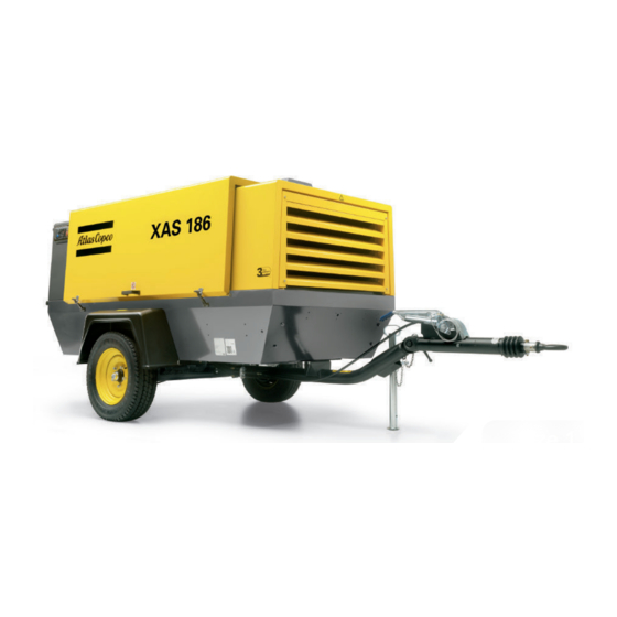
- Page 1 Instruction Manual for Portable Compressors English XAHS 186 Cud PNE Engine 6BT5.9...
- Page 3 Portable Compressors XAHS 186 Cud PNE The information provided in this book is applicable for compressors with Sr. No. PNA 814619 and onward. Printed matter N° 9096 3227 00 ATLAS COPCO (I) LTD. - PORTABLE ENERGY DIVISION www.atlascopco.com 11/2018...
- Page 4 The manufacturer does not accept any liability for any damage arising for modifications, additions or conversions made without the manufacturer's approval in writing. While every effort has been made to ensure that the information in this manual is correct, Atlas Copco does not assume responsibility for possible errors.
-
Page 5: Table Of Contents
Table of contents Preface Before starting......... 31 Starting / Stopping ........32 Please read the following instructions 4.4.1 Control panel ........32 carefully before starting to use your Operations overview ....... 34 Safety precautions ........7 compressor. Specific start procedure......34 Introduction .......... - Page 6 Engine preservation ......47 Technical specifications ......58 Storage of engine less than or up to 6 months Torque values .......... 58 from the date of engine shipment from 9.1.1 General torque values ......58 cummins plant ......... 47 Compressor / engine specifications..59 Storage of engine more than 6 months from 9.2.1 Reference conditions......
-
Page 7: Safety Precautions
Safety precautions To be read attentively and acted accordingly before towing, lifting, operating, performing maintenance or repairing the compressor. INTRODUCTION The policy of Atlas Copco is to provide the mentioned on the equipment or parts of the safety system. mechanical users of their equipment with safe, reliable unit. -
Page 8: General Safety Precautions
1 The owner responsible on Atlas Copco equipment, the mechanics non-original parts maintaining the unit in a safe operating are expected to use safe engineering modifications, additions or conversions condition. -
Page 9: Safety During Transport And Installation
6 The machinery and equipment shall be 12 Mind the markings and information SAFETY DURING TRANSPORT kept clean, i.e. as free as possible from labels on the unit. AND INSTALLATION oil, dust or other deposits. 13 In the event the safety labels are Transport of the unit has to be done by 7 To prevent an increase in working damaged or destroyed, they must be... -
Page 10: Safety During Use And Operation
- remove wheel chocks, if applied, and 7 Lifting hooks, eyes, shackles, etc., shall contact Atlas Copco. disengage the parking brake, never be bent and shall only have stress in line with their design load axis. The... - Page 11 Atlas Copco Instruction Book (AIB). as this may result in injury or death. For Keep fuel away from hot parts such as 3 When operating...
- Page 12 17 Noise, even at reasonable levels, can provided and a special warning to 23 Safety shoes should be compulsory in cause irritation and disturbance which, that effect shall be placed at each any workshop and if there is a risk, over a long period of time, may cause entrance.
-
Page 13: Safety During Maintenance And Repair
2 Parts shall only be replaced by genuine machine or undertaking major overhaul on jacks. Atlas Copco replacement parts. on it, prevent all movable parts from 13 Do not remove any of, or tamper with, 3 All maintenance work, other than rolling over or moving. -
Page 14: Tool Applications Safety
15 Protect the engine, alternator, air intake 21 When hot parts have to be handled, e.g. TOOL APPLICATIONS SAFETY filter, electrical regulating shrink fitting, special heat-resistant Apply the proper tool for each job. With components, etc., to prevent moisture gloves shall be used and, if required, the knowledge of correct tool use and ingress, e.g. -
Page 15: Specific Safety Precautions
9 (Pressure) vessel maintenance is to be in the plugs. Thus an explosive plate of the vessel: performed by Atlas Copco. atmosphere may form around the - the maximum working pressure ps in battery if ventilation is poor, and can... - Page 16 Safety valves When fitted, the lifting device should be operated at pressures not less than 75% of Operating & Maintenance the set pressure to ensure free and easy Only trained and technically competent movement of internal parts. personnel should consider overhaul, re-set The frequency of tests is influenced by or performance testing of safety valves.
-
Page 17: Leading Particulars
Leading particulars DESCRIPTION OF SAFETY GENERAL DESCRIPTION Compressor oil system PICTOGRAMS USED IN THIS The oil is boosted by air pressure. The The compressor XAHS 186 Cud is MANUAL system has no oil pump. silenced, single-stage, oil-injected screw compressor, built for a nominal effective The oil is removed from the air, in the air/ This symbol... - Page 18 This receiver pressure variation is sensed Bodywork Control panel by the regulating valve which, by means of The bodywork has openings for the intake The control panel grouping the air pressure control air to the unloader and engine and outlet of cooling air and hinged doors gauge, control switch etc., is placed at the speed regulator, matches the air output to for maintenance and service operations.
-
Page 19: Main Parts
Main parts - 19 -... - Page 20 Reference Name Reference Name Fuel Tank Alternator Minimum Pressure Valve AFce Air Filter (compressor element) Oil Cooler Air Filter (engine) OFce Oil Filter (compressor element) Air Outlet Valves Oil Filter (engine) Air Receiver Oil Level Gauge Battery Radiator Brake Handle Recovery Bottle Compressor Element Regulating Valve...
-
Page 21: Regulating System
REGULATING SYSTEM OVERVIEW - 21 -... -
Page 22: Air Flow
AIR FLOW OIL SYSTEM The oil filter by-pass valve opens when the pressure drop over the filter is above Air drawn through the airfilter (AFce) into The lower part of the air receiver (AR) normal because of a clogged filter. The oil compressor element (CE) -
Page 23: Continuous Regulating System
CONTINUOUS REGULATING SYSTEM The compressor is provided with a 2. Air inlet throttling. Part of the control air is vented to continuous regulating system and a blow- atmosphere, condensate If the air consumption is equal to or off valve (BOV) which is integrated in the discharged, through the vent holes. -
Page 24: Markings And Information Labels
Tyre pressure. Outlet. (69 psi) Danger, hot surface. Low Coolant Compressor oil drain. Electrocution hazard. Read the instruction manual Atlas Copco synthetic Battery charge indication before lifting. SCREWLUB compressor oil. Read the instruction manual Read the instruction manual Manual. before topping up with coolant. -
Page 25: Electric System
ELECTRIC SYSTEM Circuit Diagram - 25 -... - Page 26 Wiring Diagram - 26 -...
- Page 27 - 27 -...
-
Page 28: Operating Instructions
Operating instructions PARKING, TOWING AND LIFTING INSTRUCTIONS Safety precautions PARKING INSTRUCTIONS The operator is expected to apply relevant Safety precautions. Attention Before putting the compressor in to use, check the brake system. After the first 100 km travel: Check and retighten the wheel nuts and towbar bolts to the specified torque. -
Page 29: Towing Instructions
TOWING INSTRUCTIONS For both non-adjustable - and adjustable LIFTING INSTRUCTIONS towbar, the towbar should be as level as possible and the compressor and towing eye end in a level position. 1. Attach the compressor to the towing vehicle. 2. Move hand brake lever (1) in the direction of the arrow till stop. -
Page 30: Height Adjustment (With Adjustable Towbar)
• Release locking nut (1) with support HEIGHT ADJUSTMENT (WITH tools (Extension tube 2). ADJUSTABLE TOWBAR • Adjust required height of the towbar. Before towing the compressor, make sure that the joints of the • Tighten locking nut (2) by hand first. towbar secured with... -
Page 31: Before Starting
BEFORE STARTING draining operations may be determined 8. Check the air filter vacuum indicators. by experience, as the amount of If the yellow piston reaches the red condensate depends on the operating marked service range, replace the filter condition. element. Reset the indicator by pushing the reset button. -
Page 32: Starting / Stopping
STARTING / STOPPING CONTROL PANEL LED (green) Fuel ON Hourmeter LED (green) Preheat(option) Circuit breaker button LED (red) Charge indication Working pressure guage LED (red) Compressor outlet temperature Loading valve LED (red) Engine oil temperature Control module LED (red) Engine oil pressure Start/Stop button LED (red) Low coolant... - Page 33 Safety precautions Run the engine a few minutes at no-load to Fault situations protective warm up. devices (Also refer to chapter Never push the start button 6.Problem Solving): When the engine is running smoothly, when the engine is running. press loading valve (LV) and release as •...
-
Page 34: Operations Overview
• Push the start button and the starter OPERATIONS OVERVIEW SPECIFIC START PROCEDURE motor will automatically try to start the engine. During operation When the engine is running, the After cleaning /draining the fuel air outlet valves (ball valves) tanks, the system is filled with must always be put in fully air. -
Page 35: Maintenance
750, after 1500 and after 2250 The order numbers of the Service Kits are Safety during maintenance and running hours. listed in the Atlas Copco Parts List (ASL). repair. It guarantees that all necessary parts are replaced at the same time keeping down Contact Atlas Copco. -
Page 36: Preventive Maintenance Schedule For The Compressor
PREVENTIVE MAINTENANCE SCHEDULE FOR THE COMPRESSOR The schedule contains a summary of the The maintenance schedule has to be seen maintenance instructions. Read as a guideline for compressors operating in respective section before taking a dusty environment typical to compressor maintenance measures. - Page 37 Change Change Engine oil filter (3) Replace Replace Replace Fuel filter & Water seperator (3) (6) (13) Replace Replace Replace Joint of height adjustment adjustable towbar Check Grease Grease Inspection by Atlas Copco Service Technician Inspection Inspection - 37 -...
- Page 38 Technical specifications. Check coolant. Use Atlas Copco oil filters, with by-pass valve, as specified in the parts list. Replace the fuel filters regularly. Gummed or clogged filters mean fuel starvation and reduced engine performance. The quality of the fuel determines the frequency of renewal.
-
Page 39: Oil Specifications
OIL SPECIFICATIONS It is strongly recommended to Never synthetic with use Atlas Copco “screwlub”. mineral oil. This is a special oil for screw compressor which keeps the Remark: compressor excellent When changing from mineral to condition. synthetic oil (or the other way... -
Page 40: Oil Level Check
OIL LEVEL CHECK CHECK COMPRESSOR OIL LEVEL OIL AND OIL FILTER CHANGE Never mix oils of different ENGINE OIL AND OIL FILTER brands or types. CHANGE Use only non- toxic oils where there is a risk of inhaling For replacing the engine oil filter (1), delivered air. -
Page 41: Topping Up The Compressor Oil
TOPPING UP THE COMPRESSOR 3. Remove the filler plug (2) and top up When operating high ambient with oil until the pointer of the oil level temperatures, in very dusty or high gauge (1) is in the upper part of the humidity conditions, it is recommended to green area. -
Page 42: Coolant Specifications
5. Fill the air receiver until the pointer of COOLANT SPECIFICATIONS the oil level gauge is in the upper part of the green area. Be sure that no dirt gets Never remove the cooling system into the system. Reinstall and tighten filler cap while coolant is hot. -
Page 43: Coolant Check
COOLANT CHECK TOPPING UPCOOLANT REPLACING THE COOLANT Never remove the cooling system filler cap while coolant is hot. Drain For topping up / replacing The system may be under • Completely drain the entire cooling coolant consult engine operation pressure. Remove the cap slowly system. -
Page 44: Cleaning Coolers
CLEANING COOLERS Steam cleaning in combination with a cleansing agent may be applied (do not use jet at max. power). To avoid damaging the coolers, angle between jet and coolers should be approx. 90 °. Close the service door(s). Protect electrical controlling equipment,... -
Page 45: Battery Care
BATTERY CARE ACTIVATING A DRY-CHARGED RECHARGING A BATTERY BATTERY Before and after charging a battery, always check the electrolyte level in each cell; if Before handling batteries, read • Take out the battery. required, top up with distilled water only. the relevant safety precautions •... -
Page 46: Battery Maintenance
BATTERY MAINTENANCE COMPRESSOR ELEMENT OVERHAUL • Keep the battery clean and dry. When a compressor element is due for • Keep the electrolyte level above the overhaul, it needs to be done by Atlas plates or at the indicated level. Level Copco. -
Page 47: Engine Preservation
Engine preservation 3. Do not stack any material on engine box 2. Prepare the engine to fit on the to avoid damage to engine/engine box. equipment. Install the engine on the equipment and ensure the connections End user should maintain the If engine is to be stored without engine box are fitted completely. -
Page 48: Storage Of The Engine That Is Installed On The Equipment
6. Put a tag to the engine which must PREPARE THE STORED ENGINE The above procedure is to be indicate: FOR PUTTING IN SERVICE done repeatedly at the end of every six months during the • Engine preservation process date. 1. -
Page 49: Adjustments And Servicing Procedures
Adjustments and servicing procedures ADJUSTMENT OF THE CONTINUOUS REGULATING SYSTEM - 49 -... - Page 50 PRESSURE SYSTEM The working pressure is determined by the tension of the spring in the regulating valve (RV). This tension can be increased to raise the pressure and decreased to lower it by turning the adjusting wheel clockwise and anti-clockwise respectively. To adjust the normal working pressure, proceed as follows: 1.
-
Page 51: Air Filters Engine / Compressor
AIR FILTERS ENGINE / COMPRESSOR should be repeated for both air filters engine and air filters compressor. AIN PARTS The Atlas Copco air filters are 1. Release the snap clips (1) and remove specially designed the dust trap cover (2). Clean the inside application. -
Page 52: Air Receiver
AIR RECEIVER SAFETY VALVE All adjustments or repairs are to be done by an authorized representative of the safety valve (2) supplier, see section Specific safety precautions. Following checks must be carried out: • A check of the opening of the lifting gear, twice a year. -
Page 53: Fuel System
FUEL SYSTEM REPLACING FUEL FILTER ELEMENTS PRIMING INSTRUCTIONS Fuel leaked or spilled onto hot surfaces electrical components can cause a fire. To help prevent possible injury, turn the “ON/OFF” switch in position “OFF” when changing fuel filters or water separator elements. -
Page 54: Problem Solving
Choked air filter elements (AF). Remove and inspect elements. Clean or replace, if necessary. Regulating valve (RV) defective. Have regulating valve removed and inspected by an Atlas Copco Service representative. Blow down valve stuck in open position. Check and correct as necessary. - Page 55 Problem: Pressure in air receiver rises above maximum and causes safety valve to blow. Possible faults Corrective actions Regulating valve (RV) opens too late or its ball valve Have regulating valve removed and inspected by an Atlas Copco Service spring is broken. representative. Air leaks in regulating system.
- Page 56 Remove valve and check for proper opening and closing. Replace if out of position. order. Fan blade(s) broken. Check and correct if necessary. Oil stop valve malfunctioning. Remove and inspect valve. Oil separator element (OS) clogged. Have element removed and inspected by an Atlas Copco Service representative. - 56 -...
- Page 57 Alternator precautions 1. Never reverse the polarity of the battery or the alternator. 2. Never break any alternator or battery connections while the engine is running. 3. When recharging the battery, disconnect it from the alternator. Before using booster cables to start the engine, be sure of the polarity and connect the batteries correctly.
-
Page 58: Technical Specifications
Technical specifications TORQUE VALUES GENERAL TORQUE VALUES For hexagon screws and nuts with strength grade 12.9 The following tables list the recommended torques applied for Thread size Torque value (Nm / lbf.ft) general applications at assembly of the compressor. 15 (11.07) For hexagon screws and nuts with strength grade 8.8 39 (28.78) 78 (57.56) -
Page 59: Compressor / Engine Specifications
COMPRESSOR / ENGINE SPECIFICATIONS REFERENCE CONDITIONS Designation Unit XAHS 186 Cud Absolute inlet pressure bar(e) 14.5 Relative air humidity Air inlet temperature °C °F Nominal effective working pressure bar(e) The inlet conditions are specified at the air inlet grating outside the canopy. - 59 -... -
Page 60: Limitations
LIMITATIONS Designation Unit XAHS 186 Cud Minimum effective receiver pressure bar(e) Maximum effective receiver pressure, compressor unloaded bar(e) 13.5 Maximum ambient temperature at sea level without aftercooler °C °F with aftercooler °C °F Minimum starting temperature °C °F - 60 -... -
Page 61: Performance Data
PERFORMANCE DATA At reference conditions, if applicable, and at normal shaft speed, unless otherwise stated. Designation Unit XAHS 186 Cud Engine shaft speed, normal and maximum r/min 2300 Engine shaft speed, compressor unloaded r/min 1200 Free air delivery without aftercooler with aftercooler Typical oil content of compressed air mg/m... - Page 62 Free air delivery is measured according to ISO 1217 ed.3 1996 annex D • +/- 5% 25 l/s (53 cfm) < FAD < 250 l/s (530 cfm) Tolerance: • +/- 4% 250 l/s (530 cfm) < FAD • British BSI 1571 part 1 The international standard ISO 1217 corresponds to following national standards: •...
-
Page 63: Design Data
DESIGN DATA Compressor Engine Designation Number of compression stages Designation Unit All units Make Cummins Designation Unit All units Type 6BT 5.9C Compressor oil capacity 23.5 Coolant Water + Ethylene US gal 6.20 GLYCOL Fuel tank capacity Number of cylinders US gal 46.23 Bore... -
Page 64: Dataplate
Dataplate Unit serial number Name of the manufacturer Vehicle identification number A Maximum permitted laden weight of the vehicle B Maximum permitted road weight of the vehicle C Maximum permitted laden weight of the towing eye Model Working pressure Speed Engine power Manufacturing year - 64 -... -
Page 65: Disposal
Disposal GENERAL DISPOSAL OF MATERIALS When developing products and services, This concept can only succeed Atlas Copco tries to understand, address, with your help. Support us by Dispose contaminated substances and and minimize the negative environmental disposing professionally. material separately, according to local... -
Page 66: Maintenance Log
Maintenance Log Compressor ..............Customer ................. Serial number................................Service hours Maintenance action Date By initials - 66 -... - Page 67 Maintenance Log Compressor ..............Customer ................. Serial number................................Service hours Maintenance action Date By initials - 67 -...
- Page 68 Maintenance Log Compressor ..............Customer ................. Serial number................................Service hours Maintenance action Date By initials - 68 -...