Table of Contents
Advertisement
Quick Links
8413 Calibration Ct.
College Station, Tx USA
Telephone:(512)640-9896
stratusautoequip.com
Safety - Installation - Operation - Maintenance
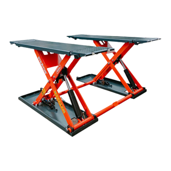
Extra Wide Commercial Grade Open Center Mobile Mid Rise
Electric Safety Lock Release Scissor Vehicle Lift
SHOWN: MS9000X
IMPORTANT NOTE:
1.
Save these instructions!
2.
This equipment should not be installed, operated or repaired without first reading instructions.
Failure to follow the instructions and safety can result in serious injury or death.
3.
Electricity should be hooked up by a certified electrician.
4.
Do NOT use equipment beyond its rated capacity.
5.
Keep manual near lift for reference
6.
By proceeding with installation and operation, you agree that you fully understand the contents of
this manual and assume full responsibility for product use.
7.
Only Operate this lift if it can be done so safely.
Models
: MS9000XT
Manual SAEMSSERIES— Revision A1 — July2023
Advertisement
Table of Contents

Related Manuals for Stratus MS9000XT


Summary of Contents for Stratus MS9000XT
- Page 1 Safety - Installation - Operation - Maintenance Extra Wide Commercial Grade Open Center Mobile Mid Rise Electric Safety Lock Release Scissor Vehicle Lift Models : MS9000XT Manual SAEMSSERIES— Revision A1 — July2023 SHOWN: MS9000X IMPORTANT NOTE: Save these instructions! This equipment should not be installed, operated or repaired without first reading instructions.
- Page 2 Stratus Auto Equipment's website. Not all of Stratus Auto Equipment lift models meet the standards as prescribed by ANSI/ALI ALCTV-(current edition) or ANSI/UL 201. Consult www.autolift.org...
- Page 3 Unit Information Be sure to document the Model Number, Serial Number, and Date of Manufacture from the label on your unit. This information is required for part or warranty issues.
-
Page 4: Table Of Contents
Exploded View Introduction This manual is designed to help customers use Stratus MS series scissor lifts. These are mid rise, with an open center that provides full under vehicle access. These lifts can be installed at ground level or flush mounted (in ground). -
Page 5: Chapter 3 Liability
Liability Stratus Auto Equipment assumes no liability for damages resulting from: •Use of the product for purposes other than those described in this manual. •Modifications to the equipment without prior, written permission from Stratus •Injury or death caused by modifying, disabling, overriding, or removing safety features. -
Page 6: Safety Instruction
Safety Instructions Make sure that you have read the User’s Manual completely including relevant instructions on installation, operation and safety before operating the lift. This lift is designed for lifting vehicles. Any other use may result in damage of the lift or injury to personnel. - Page 7 Do not modify any part of the lift without manufacturers advice. Do not make any modifications to the Lift; this voids the warranty and increases the chances of injury or property damage. If lift is not in use, lower to the lowest position and disconnect power. Be sure to cut off the power supply after the use of lift.
- Page 8 Safety Signs All safety warning labels are clearly depicted on the lift to ensure that the operator is aware of and avoids the dangers of using the lift in an incorrect manner. The labels must be kept clean and they have to be replaced if detached or damaged. Please read carefully the meaning of each label and memorize them for future operation.
-
Page 9: Chapter 5 Labels
Labels CAUTION Only trained personnel is allowed to use the lift. Read the entire manual before operating Never try to raize the vehicle exceding lift capacity Make sure you meet all safety requirements before you start working under the vehicle Surrounding of lift will remain clear when raising or lowering The manufacturer and distributor will not take... - Page 10 Measurements...
- Page 11 Frequently Asked Questions What thickness of concrete do you recommend? We recommend 6-12 inches reinforced concrete that has cured for at least 28 days. What is the recommended PSI for the concrete? We recommend a psi of 3,000 Does the lift come with anchor bolts and how many? Yes the lift comes with Anchor Bolts.
-
Page 12: Chapter 7 Warranty
Warranty 5 Years Structure - Platform, Safety Lock System 3 Years Hydraulic - Cylinder, Seal Kits, Gear Pump 2 Years Electrical - Motor, AC Contactor, PLC, Solenoid, Limiter Switches, Power Light, Buttons, Capacitors 1 Year Functional Components - Safety Covers, Hydraulic Hoses, Fittings, Reservoir, Oil/Water Regulator, Slider Blocks No Warranty Odds and Ends - Rubber Pads Packaging... -
Page 13: Chapter 10 Parameters
Parameters Model MS9000XT Rated Lifting Capacity 9,000 lbs Driving Mode Electro Hydraulic Drive Lifting Height 47 1/4" (1200 mm) Overall Length 85 1/4" (2182 mm) Overall Width 77 3/16" (1930 mm) Platform Length 62 5/8" (1590 mm) Platform Width 20 1/2" (520 mm) - Page 14 Tools Required Rotary Hammer Drill D.20 Carpenter’s Chalk Hammer Screw Sets Tape Measure (7.5m) Level Bar English Spanner (12") Lock Wrench Wrench set (10#, 13#, 14#, 15#, 17#, Pliers 19#, 24#, 27#, 30#) Ratchet Spanner With Socket Head Wrench Socket (28#) (3#, 5#, 8#) Notice The lift has been designed to be used in a covered and sheltered place, free of...
- Page 15 Site Layout Now locate the lift according to the floor plan (Figure 3), use a carpenters chalk line to layout a grid for the column locations. After the column locations are properly marked, use a chalk or crayon to make an outline of the columns on the floor at each location using the column base plate as a template.
- Page 16 Equipment Installation Please do read and understand this manual thoroughly before completing Remove the packaging and take the mechanical and hydraulic assembly to the designated installing place. Connect the oil hose to the pump assembly with a proper wrench. (Make sure the hose end is clean).
- Page 17 Precautions Check all the joints of oil hose. Only when there is no leakage, the lift can start work. Do NOT Operate lift is safety device malfunctions The machine shall not lift or lower an automobile if its center of gravity is not positioned midway of the rising platforms Otherwise, the manufacturer as well as our dealers will not bear any responsibility for any consequence resulted thereby.
-
Page 18: Chapter 17 Operation
Operation Raise the lift Make sure that you have read and understood the operation manual before operation. Drive and park the vehicle midway between two platforms. Place the four rubber pads under the prop-points of the vehicle and ensure car’s gravity has been placed on the rubber pads. - Page 19 Emergency Lowing In Case of No Power Safety Lock Not Engaged: Tie up the safety teeth on both sides with rope; pull upward the rope making the safety teeth unlocked. Having the safety teeth unlocked, manually loose the core of electro- magnetic valve on the pump assembly.
-
Page 20: Chapter 18 Troubleshooting
Troubleshooting ATTENTION: If the trouble cannot be fixed by yourself, please do not hesitate to contact us for help. We will offer our service at the earliest time we can. By the way, troubles can be judged and solved much faster if more details or pictures are be provided. - Page 21 Maintenance Easy and low cost routine maintenance can ensure the lift work normally and safely. Following are requirements for routine maintenance. You may choose the frequency of routine maintenance by consulting your lift’s working conditions and time. The Following parts need to be lubricated. Description Small idler wheel Rotor shaft...
- Page 22 Automotive Lift Institute Store You probably checked the ALI’s Directory of Certified Lifts(www.autolift.org/ali- directory-of- certified-lifts/) before making your most recent Lift purchase, but did you know the ALI Store (www.autolift.org/ali-store/) offers a wide variety of professional, easy-to-use, and reasonably priced training and safety materialsthat will make your garage a safer place to work? The ALI Store is your trusted source forworkplace safety!
- Page 23 ANNEX Packing List of the whole lift Name Drawing # / Spec. MSL 3 Mechanical Assembly MSL 3-000 Mobile Kit Optional Wheel MSL 3-A25-B1 Prop Through MSL 3-A25-B2 All Directional Wheel MSL 3-A25-B3 Feet Protector MSL 3-A1-B7 Hydraulic System MSL 3-A24 Inside Hex Screw M8*12 Overall Diagram...
- Page 24 Pneumatic Working System Air filter Pneumatic solenoid valve Pneumatic cylinder for the main platform Pneumatic cylinder for the assistant platform Hydraulic Working System Driving Cylinder Gear Pump Assistant Cylinder One-Way Valve Electrical Release Over-Flowing Valve Valve Lowering Throttle Anti-Surge Valve Valve Motor Cushion Valve...
- Page 25 Wiring Diagram...
- Page 26 Wire Connection Yellow Green Wire: Ground Wire Blue and Brown Wire: 1. If the supply voltage is 110V, either one can be 110V hot wire or neutral wire, which means if you want blue wire is 110V hot wire, the brown is neutral wire, if you want brown wire is 110V hot wire, the blue will be neutral wire.
- Page 27 Lift Diagram...
- Page 28 Size & Weight Requirements on Vehicles Note: Offers may differ as per different requirements on the version. Model (LBS (Inch) (Inch) (Inch) (LBS) (LBS) (LBS) SAE- MS900 4 5/16 5291 3527 5291 3527 13/16 3/16...
- Page 29 Special Notes Environmental damage : Only appropriately trained personnel may dismantle and dispose of the unit. Dismantling: To dismantle the product, proceed as follows: ELECTRICAL HAZARD! When carrying out any decommissioning and dismantling work on the unit, switch off all power supply connections, ensure they cannot be switched on unintentionally and verify that they have been disconnected.
Need help?
Do you have a question about the MS9000XT and is the answer not in the manual?
Questions and answers
lift halfway up on locks.push down button to go down.is there an adjustment for how high the lift goes before coming down
Yes, there is an adjustment for the lowering speed before the Stratus MS9000XT lift comes down. You adjust the hydraulic oil flow valve by turning the middle hexagonal screw counterclockwise to set the lowering speed to 0.5 in/sec or slower.
This answer is automatically generated