Table of Contents
Advertisement
Quick Links
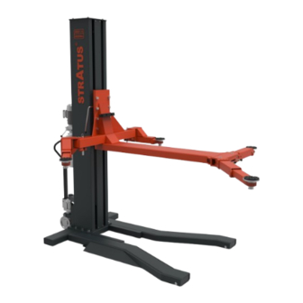
STRATUS Single Post Lift Installation & Operation & Maintenance Instructions
Model No. SAE-S66M
Single Post Lift
Single (1) Point Manual Release
Lifting Capacity 6600lbs
Important Note
1.This equipment can not be installed, operated or repaired without reading instructions.
2.Electricity must be hooked up by certified electrician.
3.Do not use this equipment beyond its rated capacity.
Installation&Operation
Maintenance Instructions
Advertisement
Table of Contents

Related Manuals for Stratus SAE-S66M


Summary of Contents for Stratus SAE-S66M
- Page 1 STRATUS Single Post Lift Installation & Operation & Maintenance Instructions Model No. SAE-S66M Installation&Operation Single Post Lift Single (1) Point Manual Release Maintenance Instructions Lifting Capacity 6600lbs Important Note 1.This equipment can not be installed, operated or repaired without reading instructions.
-
Page 2: Table Of Contents
Directory 1-Main features of the equipment……………………………………………………………………………………………………………………………………………………3 1.1-Product description…………………………………………………………………………………………………………………………………………………………………3 1.2-Features of the product……………………………………………………………………………………………………………………………………………………………3 1.3-Safety Marking of products………………………………………………………………………………………………………………………………………………………3 2-Basic parameters of equipment……………………………………………………………………………………………………………………………………………………4 3-Spare parts in the accessories box…………………………………………………………………………………………………………………………………………………5 4-Shape and size of equipment………………………………………………………………………………………………………………………………………………………5 4.1-Product structure group……………………………………………………………………………………………………………………………………………………………5 4.2-Shape and size of equipment……………………………………………………………………………………………………………………………………………………6 5-Installation of equipment……………………………………………………………………………………………………………………………………………………………7 5.1-Installation of columns and bases………………………………………………………………………………………………………………………………………………7 5.2-Installation of carriage and lifting platform……………………………………………………………………………………………………………………………………7 5.3-Swing arm lock shaft assembly……………………………………………………………………………………………………………………………………………………8... -
Page 3: 1-Main Features Of The Equipment
1-Main features of the equipment 1.1-Product description Model: SAE-S66M is a hydraulic lift, the whole product can move, with electronic control box, easy to operate. It is suitable for 6600lbs or less inspection, repair and maintenance of various types of vehicles. -
Page 4: 2-Basic Parameters Of Equipment
2-Basic parameters of equipment Model SAE-S66M Lifting capacity 6600lbs(3000Kg) Max lifting height 74 13/16″(1900mm) Min height 3 9/16″(90mm) Lifting time About 50 Sec. Lowering time About 40 Sec. Column Thickness of Steel 5.5mm Carriage Thickness of Steel 12mm/20mm Arms Thickness of Steel 15 3/16"-25 9/16"(386-650mm) -
Page 5: 3-Spare Parts In The Accessories Box
3-Spare parts in the accessories box. Serial Name Photo Parameter Quantity number Swing arm big support arm combination and Hexagon Screw block assembly connection screw Column and base connecting screw Hexagon Screw Hexagon Screw M8×25 Power unit fixing screws Anti-collision tape Hexagon socket screws Heightening sleeve bracket fixing screw Hose... -
Page 6: Shape And Size Of Equipment
4.2-Shape and size of equipment... -
Page 7: 5-Installation Of Equipment
5-Installation of equipment 5.1-Installation of columns and bases 1.Base 2. Column 3. Flat pad Φ20 4. Spring mat Φ20 5.Hexagon bolt M20×50 5.2-Installation of carriage and lifting platform 1. Carriage 2. Lifting platform 3. Hexagon bolt M18×50 4. Spring mat Φ18 5. -
Page 8: Swing Arm Lock Shaft Assembly
5.3-Swing arm lock shaft assembly 1.Swing arm lock shaft lifting ring 2.CirclipΦ16 3.Small square lock spring 4.Swing arm lock shaft 5.Small square lock tooth 6.Swing arm lock small shaft 5.4-Arm assembly 1.Right swing arm welding 2.Left side swing arm welding 3.Front support has welding 4.Swing arm rear axle welding 5.Front arm shaft welding... -
Page 9: Power Unit Installation
5.5-Power unit installation 1.Column assembly 2. Power unit 3. Hose 4.Hexagon screw M8×30 5. Spring cushionΦ8 6.Flat padΦ8 7.Hex nuts M8 5.6-Mobil kit installation 1. Hydraulic lifting assembly 2. Hydraulic lifting shaft 3. Axle clip spring Φ25... -
Page 10: Wire Connection
5.7-Wir connection **Important Information** Pressure Valve: Clockwise adjustment increases pressure to make the power unit to have more power, counterclockwise adjustment decreases pressure to make the power unit to have less power. Hydraulic Oil flow valve: Clockwise adjustment to speed up, counterclockwise adjustment to slow down. -
Page 11: 6-Operation And Commission Of Equipment
6-Operation and commission of equipment 6.1-Instructions for operating 6.1.1 Check all joints and tubing connections. The machine can only be used if there is no oil leak. 6.1.2 If the safety device of the lift fails, it must not be put into use. 6.1.3 If the center of gravity of the repaired vehicle is not located in the center of lift range, Anybody can not operate the lift, otherwise the manufacturer and dealers do not bear any consequences. -
Page 12: 7-Maintenance And Inspection Of Equipment
7-Maintenance and inspection of equipment Item Method Period Arm Safety lock Gear Manually check arm safety lock teeth for occlusion and complete lock. Everyday Assembly Spiral base Check the lift arm, clean and replace the rubber base. Everyday Oil Cylinder and Oil Before using the lift, check for oil leakage Everyday pipe joint... -
Page 13: 8-Common Trouble Shooting
8-Common trouble shooting Troubles Reason Solution Any friction marks on the inside of the cylin- Grease the inside of the column. Find out unusual sound If there’s an obstruction in the cylinder Clear the obstacle. Bad wire contact Check and connect the lines. The Motor doesn’t turn, it Motor broken and burnt out Replace Motor. -
Page 14: 9-Structures And Parts List
9. Structures and parts list 9.1 Slide carriage exploded view Name Specifications Qty. Weld carriage assemble Inner hex column bolt GB/T70.1-2000 M6x16 Column roller bearing GB/T283-94 NUP2308M Slide wheel A - type shaft keep off ring GB/T894.1-1986 40 A - type bore keep off ring GB893.1-8390... -
Page 15: Loading Supporting Arm Exploded View
9.2 Loading supporting arm exploded view Name Specifications Qty. Three group screw plate φ50 Height set A-type shaft keep off ring GB/T894.1-1986 50 Cross tray bolt GB/T 818-2000 M6X12 Main supporting beam Inner hex column bolt GB/T70.1-2000 M6x12 Cross tray bolt GB/T 818-2000 M6X12 Rear weld assemble Rear extendable arm assembly... -
Page 16: Driven System Exploded View
9.3-Driven system exploded view Name Qty. Pipe connecting Cylinder Cylinder cover Cylinder guide Dust proof ring Y- type seal ring Guide ring O - type ring Trolley base Chain wheel Spring washer Cross tray bolt Welded wheel shaft Non oil bearing Plate chain Placket pin Chain connecting shaft... -
Page 17: Base Assembly
9.4-Base assembly Name Qty. Base welding Base roller shaft Base roller Oil-free bearing Circlip 9.5-Casting front arm assembly Name Qty. Cast front support arm Mobile arm welding Oil-free bearing Casting front arm crescent teeth Socket head cap screws M10×20 Flat head hexagon socket screw M8×20 Rubber pad Pallet welding Tray adjustment sleeve 1... -
Page 18: Swing Arm Left Support Arm Assembly
9.6-Swing arm left support arm assembly Name Qty. Welding of left arm of swing arm Mobile arm welding Swing arm moon teeth Flat pad Φ10 Spring cushion Φ10 Hex bolts M10×35 Socket head cap screws M10×12 Flat head hexagon socket screw M8×20 Rubber pad 10 Pallet welding... -
Page 19: Block Assembly
9.8-Block assembly Name Qty. No. Name Qty. Manual lock trolley welding 15 Welding of manual lock card wheel support plate Shaft bowl 16 Manually unlock the tension spring Bearing-NU308E 17 Manual lock wheel connecting rod welding Nylon bushings on both sides of the trolley 18 Hex nuts M6 Nylon sleeve 19 Manually unlock the card wheel support plate shaft...
Need help?
Do you have a question about the SAE-S66M and is the answer not in the manual?
Questions and answers