Table of Contents
Advertisement
Quick Links
Model No.:SAE-F10S
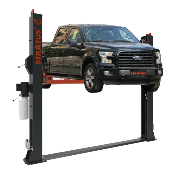
Two Post Lift
Manual Single Point Lock Release
Lifting Capacity:10000 LBS
Important Note
1.This equipment cannot be installed, operated or repaired without reading instructions.
2.Electricity must be hooked up by certified electrician.
3.Do not use this equipment beyond its rated capacity.
STRATUS
2 Post Lift Installation/Operation &Maintenance Instructions
Installation &Operation
Maintenance &Instructions
Advertisement
Table of Contents

Related Manuals for Stratus SAE-F10S


Summary of Contents for Stratus SAE-F10S
- Page 1 STRATUS 2 Post Lift Installation/Operation &Maintenance Instructions Model No.:SAE-F10S Installation &Operation Two Post Lift Maintenance &Instructions Manual Single Point Lock Release Lifting Capacity:10000 LBS Important Note 1.This equipment cannot be installed, operated or repaired without reading instructions. 2.Electricity must be hooked up by certified electrician.
-
Page 2: Table Of Contents
CONTENTS 1-The main features of the equipment………………………………………………………………………………………3 1.1-Product description………………………………………………………………………………………………………3 1.2-Features of the product…………………………………………………………………………………………………3 1.3-Satey mark of the product………………………………………………………………………………………………3 2-Technical Date of the equipment…………………………………………………………………………………………4 2.1-Product Dimensions………………………………………………………………………………………………………5 3-Equipment appearance and dimensions…………………………………………………………………………………5 3.1-Structure……………………………………………………………………………………………………………………5 3.2-Installation requirement…………………………………………………………………………………………………6 4-Installation of equipment…………………………………………………………………………………………………7 4.1-Foundation requirements………………………………………………………………………………………………7 4.2-Installation steps…………………………………………………………………………………………………………8 4.3-Column Installation………………………………………………………………………………………………………11 4.4-Installation of balanced wire rope………………………………………………………………………………………11 4.5-Connect and unlock the thin wire rope………………………………………………………………………………12 4.6-Installation power unit, lock cover and height adapter bracket……………………………………………………12... -
Page 3: 1-The Main Features Of The Equipment
1-The main features of the equipment 1.1-Product description This product is a hydraulic lift. The product is manual single point lock release, easy to operate. It is suitable for in- spection, repair and maintenance of a vehicles below 10000LBS. 1.2-Features of the product When the power unit of the hydraulic lift is connected to the power supply ,press the switch, the gear pump works, and the hydraulic oil pushes the piston rod up, which is brought to the pulley and the pulley and the safety lock tooth will blink and bite each other during each ascent. -
Page 4: 2-Technical Date Of The Equipment
2-Technical Date of the equipment Model SAE-F10S Lifting capacity 4500KG/1000lbs Lifting height 2000mm/78 3/4″ Min height 110mm/4 5/16″ Width between columns 2880mm/113 3/8″ Drive through 2572.6mm/101 1/4″ Lifting time About 40 Sec. Lowering time About 30 Sec. Column thickness 5.5mm / 1/4″... -
Page 5: Product Dimensions
2.1- Product Dimensions 3-Equipment appearance and dimensions 3.1-Structure Composition POS. Name Main column assembly Sub-column assembly Power unit Carriage Anti-collision tape Two-section arm assembly Three-section arm assembly Floor plate Single layer spiral tray Plastic buckle cover Heightening bracket Increase the set... -
Page 6: Installation Requirement
3.2- Installation requirement Tools required: electric hand drill (drill bits D16 and D18),open spanner (D17-19),movable spanner, Phillips screw- driver, slotted screwdriver, horizontal instrument, hammer, band tape, etc. Name Picture Rotary hammer drill(Φ19) carpenter's chalk Hammer Screw Sets Level bar Tap measure English spanner(12") Pliers Ratchet spanner with socket(28#) -
Page 7: 4-Installation Of Equipment
4-Installation of equipment 4.1-Foundation requirements Specification of concrete must be adhered to the specification as following. Failure to do so may result in lift and /or vehicle falling. ◇ Concrete must be thickness 200mm minimum and without reinforcing steel bars, and must be completely dry before lift installation. -
Page 8: Installation Steps
4.2- Installation steps Step 1:Check the pats before assembly Packaged lift and hydraulic power unit. Step 2:Move aside the parts and check the parts according to the shipment parts list . - Page 9 Step 3: Spare parts in the accessories box. Serial Name Photo Parameter Quantity number Arm shaft Φ40×168mm Arm shaft elastic cylindrical pin Φ6×50mm Increased set 1 Φ50×45L Increased set 2 Φ50×70L Anti-collision tape Hexagon socket screws Anti-collision tape strip fixing screws M8×30 Expansion screw M20×160L...
- Page 10 Step 4: Install anchor bolts Position the columns on the installation layout of baseplate. Install the anchor bolts. Check the columns plumbness with level bar, and adjusting with the shims if the columns are not vertical. Do not tighten the anchor bolts . Note: Anchor bolts driven into the ground at least 150mm.
-
Page 11: Column Installation
4.3-Column Installation 4.3.1- Lift the carriage to the first lock position to ensure that the mechanical lock is locked in place to facilitate the installation of expansion bolts. 4.3.2- According to the dimensions of foundation, measure the position of the main and auxiliary columns, check the position and dimensions of the bottom plate, and drill the expansion screw fixing holes, clean up the drilling dust. -
Page 12: Connect And Unlock The Thin Wire Rope
4.5-Connect and unlock the thin wire rope Name Qty. Manual unlocking lever Unlock the wire rope Locking and unlocking rope seat assembly accessories Unlock the rope seat 4.6-Installation of hydraulic power unit, lock cover, height adapter bracket Name Qty. Safety lock cover Phillips round head screws M6×8 Hex nuts M8 Power unit... -
Page 13: The Connection Of The Hoses
4.7-The connection of the hoses Name Qty. Main cylinder Auxiliary cylinder Hose 1 Hose 2 Power unit Connection connector 4.8-The connection of the lines... -
Page 14: Arms Installation
Pos. Name Motor Check Valve Connect to Hydraulic Hose Pressure Valve Dump Valve Hydraulic Oil Filling Port Unloading Valve Stem Oil Drum Hydraulic Oil Flow Valve 10 Optional Hydraulic Hose Connection Hole 11 Power line 12 Limit Switch Wire **Important Information** Pressure Valve: Clockwise adjustment increases pressure to make the power unit to have more power, counterclockwise adjustment decreases pressure to make the power unit to have less power. -
Page 15: Filling With Hydraulic Oil
4.10-Filling the hydraulic oil Attention: Please use the new hydraulic oil. The capacity of the oil tank is 10L. Do not fill the oil tank completely. The hydraulic oil must be 4/5 or more of the capacity of the oil tank to work normally. Use 32# in winter and 46# anti-wear hydraulic oil in summer. -
Page 16: 6-The Maintenance And Inspection Of Equipment
6-The maintenance and inspection of the equipment Name Methods Period Pos. Manually check the occlusion of the arm safety lock tooth Arm Safety lock tooth Every day and whether they can be completely locked. Spiral pad combination Check the rubber pad, clean and replace also. Every day Check the cooperative relationship between the safety lock Column safety lock combination... -
Page 17: 7-Troubleshooting Of Common Faults
7. Troubleshooting of common faults Fault Reason Methods Are there any abrasion marks inside the col- Add some lubricant oil into the umn? column. Abnormal sound is found. Are there any obstacles in the column? Chin up the obstacles. The cables connection is not good. Check and connect the lines. -
Page 18: 8-Explosion Picture Of The Product
8. Explosion picture of the product 8.1 Appearance explosion picture Pos. Name Qty. Pos. Name Qty. Main column assembly Power unit Sub-column assembly Limit switch Block assembly Phillips round head screws M5×10 Two-section support arm combination Phillips round head screws M5×25 Three-section arm combination Upper cover welding Cylinder... - Page 19 8.2 Assembling of the safety lock for the main column Pos. Name Qty. Pos. Name Qty. Main column safety lock cover Unlock the rope seat welding Phillips round head screws M6×8 Small nylon wheel Handball Circlip Φ9 Unlock lever Safety tip lock Hex nuts M10 Bolt seat Circlip Φ20...
- Page 20 8.3 Assembling of the safety lock for the auxiliary column Pos. Name Qty. Pos. Name Qty. Secondary column safety lock cover Top wire M6×10 Phillips round head screws M6×8 Unlock the rope seat Circlip Φ20 Torsion spring Flat pad Φ20 Safety lock shaft Door spring Unlock the thin wire rope...
- Page 21 8.4 Carriage Assembling Pos. Name Qty. Block welding Slider Half round gear shaft Hollow pin Φ5×30 Half round gear shaft spring Half round tooth Small lock washer Hollow pin Φ5×35 Arm shaft Anti-collision rubber block Socket head cap screws M8×30 8.5 Oil cylinder assembly Pos.
- Page 22 8.6 Two-stage arm assembling Pos. Name Qty. Pos. Name Qty. Two-section long boom welding Phillips round head screws M8×20 Two-section long two-arm welding Socket head cap screws M10×14 Socket head cap screws M6×8 Phillips round head screws M5×8 Two-section spiral sleeve Tool box (Optional) Two-section pallet welding Moon teeth...
- Page 23 8.7 Three-sections arm assembling Pos. Name Qty. Pos. Name Qty. Three-section boom welding Phillips round head screws M8×20 Three-section arm welding Phillips round head screws M8×10 Three-section arm forearm welding Socket head cap screws M10×14 Socket head cap screws M6×8 Hex bolts M10×35 Two-section spiral sleeve Moob teeth...
Need help?
Do you have a question about the SAE-F10S and is the answer not in the manual?
Questions and answers