Table of Contents
Advertisement
Quick Links
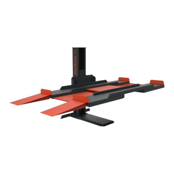
Single Post Parking Lift Installation & Operation & Maintenance Instructions
Model No.:SAE-P166M
●
Single Posting Lift
●
Single (1) Point Manual Release
●
Lifting Capacity:6600LBS
Important Note
1.This equipment can not be installed, operated or repaired without reading instructions.
2.Electricity must be hooked up by certified electrician.
3.Do not use this equipment beyond its rated capacity.
Installation & Operation
Maintenance & Instructions
Advertisement
Table of Contents

Related Manuals for Stratus SAE-P166M


Summary of Contents for Stratus SAE-P166M
- Page 1 Single Post Parking Lift Installation & Operation & Maintenance Instructions Model No.:SAE-P166M ● Single Posting Lift Installation & Operation ● Single (1) Point Manual Release Maintenance & Instructions ● Lifting Capacity:6600LBS Important Note 1.This equipment can not be installed, operated or repaired without reading instructions.
-
Page 2: Table Of Contents
Table of contents 1-Table of content………………………………………………………………………………………………………3 1.1-Product Feature………………………………………………………………………………………………………3 1.2-Safety lock structure…………………………………………………………………………………………………3 2-Basic parameters of the equipment……………………………………………………………………………………4 2.1-Product Dimensions…………………………………………………………………………………………………4 2.2-Product structure……………………………………………………………………………………………………5 2.3-Tools required before installation……………………………………………………………………………………5 3-installation steps………………………………………………………………………………………………………6 3.1-Check the components of the lift before installation………………………………………………………………6 3.2-Check the standard parts in the accessories box, etc.………………………………………………………………6 3.3-Equipment installation space………………………………………………………………………………………8 3.4-Foundation preparation for installation……………………………………………………………………………8 3.5-Chassis and foot angle iron installation……………………………………………………………………………8... -
Page 3: 1-Table Of Content
1-The main performance of equipment The product is a hydraulic lift .The product is manually unlocked, easy to operate, suitable for parking of various mod- els below 6600LBS. 1.1-Product Features When the hydraulic lift is powered on through the power unit, press the button switch, the gear pump works, the hy- draulic oil pushes the piston rod up, and is brought up by the chain to the pulley and the lifting arm, so as to achieve the purpose of lifting;... -
Page 4: 2-Basic Parameters Of The Equipment
2-Basic parameters of the equipment Lifting capacity 6600LBS/3000KG Motor voltage 220V Max lifting height 78 3/4″/2000mm Power 2.2Kw Min height 4 15/16″/215mm Frequency 60Hz Platform length 152″/3860mm Breaker Platform width 24″/609mm Hydraulic oil AW46/AW32 155″×30″×38″ Platform space 34 5/8″/880mm Shipping Size 3920×740×960mm Lifting time About 60s... -
Page 5: Product Structure
2.2-The structural group of the product (as shown in the figure) Name Name Post welding created by self Platform Support Left Arm Welding created by self Upper cover created by self Platform Support Right Arm Welding created by self limit switch Purchased parts connecting yoke created by self... -
Page 6: 3-Installation Steps
3- Installation steps 3.1- Please check the parts of the lift before installation (as shown in the picture) 3.2- Check the standard parts, etc. in the accessory box (as shown in the table below) Sec. Name Photo Specification Outer hex bolt with elastic flat washer and M16×50 hex nut Expansion screw... - Page 7 Sec. Name Photo Specification Hexagon socket screw with elastic flat half buckle M12×180 washer and hex nut Hexagon socket screw with elastic flat half buckle M12×130 washer and hex nut Hexagon socket screw with elastic flat half buckle M12×80 washer and hex nut fender cover power unit backpack Hexagon socket head screw with elastic...
-
Page 8: Equipment Installation Space
3.3-Equipment installation space According to the external dimension drawing of the product; the lift must be at least 1 meter away from other fixed objects (such as the wall) to ensure that there is enough space to ensure that the vehicle can be driven on and off the lifting platform;... -
Page 9: Post Mount
3.7- Column installation (as shown in the picture) Name Spec Column assembly created by self Hex bolts Standard Parts M20×60 spring washer φ20 Standard Parts Flat pad φ20 Standard Parts 3.8 - Attachment yoke installation (as shown in the picture) Name Spec Column assembly... -
Page 10: Platform Yoke Installation
3.9-Platform yoke installation (as shown in the picture) Name Spec Column assembly created by self Joining Yoke Welding created by self Platform support right fork arm welding created by self Platform support left fork arm welding created by self Hex nuts Standard Parts spring washer Φ20... -
Page 11: Platform Installation
3.10-Platform installation (as shown in the figure) Name Spec Purchased parts created by self Platform left fork arm welding created by self Platform right fork arm welding created by self Socket head cap screws Standard Parts M12×180 Flat pad Φ12 Standard Parts spring washer Φ12... -
Page 12: Dust Tray Installation
3.11-Dust tray installation (as shown in the figure) Name Spec Dust tray2 created by self Dust tray1 created by self Dust tray created by self Phillips button Standard Parts M6×20mm head screw Flat pad φ6 Standard Parts Hex nuts Standard Parts Approach board created by self 3.12-Installation of car fender (as shown in the figure) -
Page 13: Power Unit Installation
3.13-Power unit installation (as shown in the figure) Note: The power unit can be installed on both sides of the column, which can be selected according to the needs of customers; Name Spec power unit Purchased parts power unit backpack created by self Flat pad φ6... -
Page 14: Power Unit Description
3.15-Description of each component of the power unit Functional description of each part of the power unit **Important Information** Pressure Valve: Clockwise adjustment increases pressure to make the power unit to have more power, counterclock- wise adjustment decreases pressure to make the power unit to have less power. Hydraulic Oil flow valve: Clockwise adjustment to speed up, counterclockwise adjustment to slow down. -
Page 15: 4-Check After Installation
4-Check after installation Whether the expansion bolts are installed in place; Whether the button stops when the hand is released; Whether the sensitivity of the limit switch is valid; Rise and fall without jitter; no abnormal noise; Check whether the fixing bolts, nuts and circlips are loose; There is no oil leakage at the oil pipe connection;... -
Page 16: 5-Equipment Maintenance And Inspection
5-Maintenance and inspection of equipment Name Method Cycle Oil cylinder and oil Before using the lift, check for oil leakage; every day pipe joint control button every day Check whether the button is "press to run, hand off to stop"; Check whether the security lock can be unlocked and locked simultane- safety lock combina- every day... -
Page 17: 6-Troubleshooting
6- Troubleshooting of common faults Symptoms reason solution Are there any traces of friction inside the Add lubricating oil inside the cylin- cylinder? Unusual sound found Is there any obstacle in the column to clear Bad wire contact Check and connect the wiring The motor does not turn and does The motor is disconnected and burned replace the motor...
Need help?
Do you have a question about the SAE-P166M and is the answer not in the manual?
Questions and answers