Table of Contents

Subscribe to Our Youtube Channel
Related Manuals for Stratus SAE-P49


Summary of Contents for Stratus SAE-P49
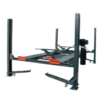
- Page 1 Installation, Operation Model No. SAE-P49 and Parts Manual 4 Post Parking Lift Single Point Manual Release Lifting Capacity 9,000 lbs Read this entire manual carefully and completely before installation or operation of the lift.
-
Page 2: Table Of Contents
Installation, Operation and Parts Manual INDEX 1.IMPORTANT SAFETY INSTRUCTIONS ......................3 1.1 Important notices ............................. 3 1.2 Qualified personnel ............................3 1.3 Danger notices .............................. 3 1.4 Training................................. 4 1.5 Warning signs ............................... 4 2.OVERVIER OF THE LIFT ............................ 5 2.1 General descriptions ............................ -
Page 3: Important Safety Instructions
Installation, Operation and Parts Manual 1.IMPORTANT SAFETY INSTRUCTIONS 1.1 Important notices We will offer one-year's quality warranty for the whole machine,during which any quality problem will be properly solved to the user's satisfaction. However, we will not take any responsibility for whatever bad consequence resulted from improper installation and operation, overload running or unqualified ground condition. -
Page 4: Training
Installation, Operation and Parts Manual b. Empty the oil tank; c. Lubricate the moving parts with hydraulic oil. 1.4 Training Only these qualified people, who have been properly trained, can operate the lift. We are quite willing to provide professional training for the users when necessary. Attention: For environment protection, please dispose the disused oil in a proper way. -
Page 5: Overvier Of The Lift
Therefore, no slipping will happen in case the hydraulic system beaks down. Safety structure: 2.2 Technical data Model Lifting capacity Lifting time Lifting height Overall Height Overall Width Width between posts SAE-P49 9000 lbs 60 Sec 86 5/8” 95 1/2” 136 1/16” 112 5/8" 2.3 Construction of the lift... -
Page 6: Installation Instructions
Installation, Operation and Parts Manual 3.INSTALLATION INSTRUCTIONS 3.1 Preparations before installation 3.1.1 Tools and equipment needed ✓ Appropriate lifting equipment ✓ Anti-abrasion hydraulic oil. ✓ Rotary Hammer Drill with 3/4’’ drill bit. ✓ Chalk and tape measure, magnetic plump, 8 metersФ15 level pipe. ✓... - Page 7 Installation, Operation and Parts Manual space for installation and use. 1. Plan the final installation position of the lift according to the installation foundation drawing (Appendix 2) and the external dimension drawing (Appendix 1). 2. Determine the assembly site. The ground between the assembly site and the final installation location must be flat and free of obstacles, so that the lift can be moved to the final installation location (a mobile frame is required).
- Page 8 Installation, Operation and Parts Manual self-locking plate; 8. Turn the auxiliary platform over, with the mouth facing down, and move it to the corresponding position of the main platform; 9. Fix the sub-platform to the beam. Step8: Install the hydraulic system. 1.
- Page 9 Installation, Operation and Parts Manual Step13: Adjust the device. 1. Press the lower handle of the power unit to lock the device, and check whether the four insurances are locked in the same height slot at the same time; 2. Adjust the height of the self-locking board to make the platform basically level (check with a transparent water pipe or a horizontal ruler);...
-
Page 10: Operation Instructions
Installation, Operation and Parts Manual 4.OPERATION INSTRUCTIONS 4.1 Precautions 4.1.1 Check all the joints of oil hose. Only when there is no leakage, the lift can start work. 4.1.2 The lift, if its safety device malfunctions, shall not be used. 4.1.3 The machine shall not lift or lower an automobile if its center of gravity is not positioned midway of the lifting arms. - Page 11 Installation, Operation and Parts Manual 3. Place the rubber pads on the rear wheels of the vehicle. 4. Make sure to connect according to the power mark on the machine nameplate. 5. First ascend a short distance (about 700-800mm from the ground), check whether the operation is normal, press the descending handle lightly, and check whether the insurance is reliable.
-
Page 12: Trouble Shooting
Installation, Operation and Parts Manual 5.TROUBLE SHOOTING ATTENTION: If the trouble could not be fixed by yourself, please do not hesitate to contact us for help .We will offer our service at the earliest time we can. By the way, troubles could be judged and solved much faster if more details or pictures could be provided. -
Page 13: Maintenance
Installation, Operation and Parts Manual 6.MAINTENANCE Easy and low cost routine maintenance can ensure the lift work normally and safely. Following are requirements for routine maintenance. Frequency of routine maintenance is determined by working condition and frequency. The following parts need lubrication. Name Slider in beam Wire rope pulley in beam... -
Page 14: Annex
Installation, Operation and Parts Manual 7.ANNEX Annex1, Overall diagram... -
Page 15: Annex2, Floor Plan
Installation, Operation and Parts Manual Annex2, Floor plan... -
Page 16: Annex3, Hydraulic Working System
Installation, Operation and Parts Manual Annex3, Hydraulic working system 1. Oil cylinder 2. Pipe explosion-proof valve 3. Manual unloading valve 4. Check valve 5. Motor 6. Gear pump 7. Oil filter 8. Buffer valve 9. Relief valve 10. Adjustable flow valve 11. -
Page 17: Annex4, Electrical Schematic
Installation, Operation and Parts Manual Annex4, Electrical schematic 110V/1PH/60HZ... -
Page 18: Annex 5,Separate Diagrams For The Lift
Installation, Operation and Parts Manual Annex 5,Separate diagrams for the lift... - Page 19 Installation, Operation and Parts Manual Name Drawing number (Specification) Material Remarks Nut M18 GB/T 6170 Column top plate ON-7440PB-010-00 Bolt M12×30 GB/T 5781 Nut M12 GB/T 6170 Flat pad 12 GB/T 95 Spring pad 12 GB/T 93 Deputy column ON-7440PB-200-00 Self-locking plate ON-7440PB-020-00 mobile rack...
- Page 20 Installation, Operation and Parts Manual Name Drawing number (Specification) Composite gasket G1/4 pump connector High pressure oil pipe 2000 ON-7436P-000-08 Thin Nut G1/4 Bulkhead Right Angle ON-7224E-A4-B15 Fittings High pressure oil pipe 1850 ON-7440PB-000-14 Cylinder joint ON-7436P-000-30...
- Page 21 Installation, Operation and Parts Manual Name Drawing number (Specification) Thin Nut M20 GB/T 6172 Nut M20 GB/T 6170 Spacer 20 GB/T 95 Wire Rope III ON-7440PB-000-12 Wire Rope IV ON-7440PB-000-13 Wire rope I ON-7440PB-000-10 Wire Rope II ON-7440PB-000-11...
- Page 22 Installation, Operation and Parts Manual Name Drawing number (Specification) Handle ball M10×30 ON-7224T-A2-B3-C6 handle bar ON-7440PB-061-00 short tie rod ON-7440PB-000-03 Bolt M8×30 GB/T 5781 Self-locking nut M8 GB/T 889.1 connecting screw ON-7436P-060-02 Nut M12 GB/T 6170 double screw ON-7440PB-000-05 link ON-7440PB-091-00 casing ON-7440PB-000-09...
- Page 23 Installation, Operation and Parts Manual Name Drawing number (Specification) Remarks Bolt M8×30 GB/T 5781 Flat pad 8 GB/T 95 slider ON-7440PB-400-01 beam body ON-7440PB-410-00 Bolt M8×50 GB/T 5781 insurance shaft ON-7440PB-400-02 rope break insurance ON-7436PB-430-00 Manual insurance ON-7440PB-420-00 wire rope pulley ON-7440PB-000-01 Composite Bushing 3520 Wire rope pulley...
- Page 24 Installation, Operation and Parts Manual Name Drawing number (Specification) Bolt M8×25 GB/T 5781 Flat pad 8 GB/T 95 spring pad 8 GB/T 93 Wire rope pulley ON-7440PB-040-00 wire rope pulley ON-7440PB-000-01 Composite Bushing 3520 Sleeve 45 ON-7440PB-000-07 Bolt M10×120 GB/T 5780 main platform ON-7440PB-500-00 Cylinder 70/25/2050...
- Page 25 Installation, Operation and Parts Manual Name Drawing number (Specification) Wheel fork ON-7440PB-610-00 Bolt M10×25 GB/T 5781 Nut M10 GB/T 6170 Flat pad 10 GB/T 95 spring pad 10 GB/T 93 Universal wheel Pin 245 ON-7440PB-620-01 R pin 3.5×70...
Need help?
Do you have a question about the SAE-P49 and is the answer not in the manual?
Questions and answers