Table of Contents
Advertisement
Quick Links
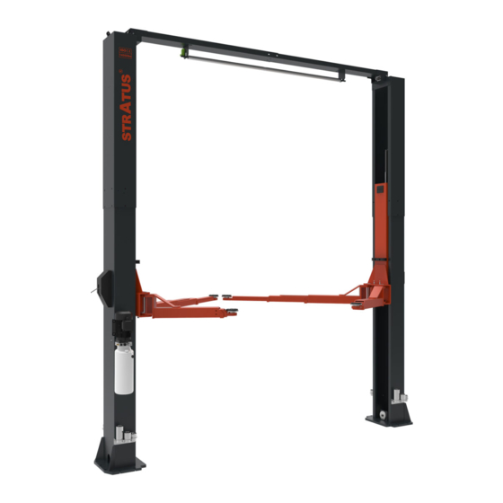
STRATUS
Model No.: SAE-C12X
2 Post Overhead Lift
Single (1) Point Manual Release
Lifting Capacity:12000LBS
Important Note
1.This equipment can not be installed, operated or repaired without reading instructions.
2.Electricty must be hooked up by certified electrician.
3.Do not use this equipment beyond its rated capacity.
2 Post Overhead Lift Installation & Operation & Maintenance Instructions
Installation & Operation
Maintenance & Instructions
Advertisement
Table of Contents

Related Manuals for Stratus SAE-C12X


Summary of Contents for Stratus SAE-C12X
- Page 1 STRATUS 2 Post Overhead Lift Installation & Operation & Maintenance Instructions Model No.: SAE-C12X 2 Post Overhead Lift Installation & Operation Single (1) Point Manual Release Maintenance & Instructions Lifting Capacity:12000LBS Important Note 1.This equipment can not be installed, operated or repaired without reading instructions.
-
Page 2: Table Of Contents
CONTENTS ………………………………………………………………………………………………… 1-Equipment description 1.1-Description ……………………………………………………………………………………………………………3 1.2-Technical specifications………………………………………………………………………………………………3 1.3-Installation requirement………………………………………………………………………………………………5 2-Specifications of concrete………………………………………………………………………………………………6 3-Installation steps…………………………………………………………………………………………………………7 4-Operation and use………………………………………………………………………………………………………18 4.1-Operation ……………………………………………………………………………………………………………18 4.2-Raising Lifting…………………………………………………………………………………………………………18 4.3-Stopping ………………………………………………………………………………………………………………18 4.4-Lowering ………………………………………………………………………………………………………………18 5-Safety ……………………………………………………………………………………………………………………18 5.1-Important Reminder…………………………………………………………………………………………………18 5.2-Vehicle Position………………………………………………………………………………………………………19 5.3-Risk of Vehicle falling off from the lift…………………………………………………………………………19 6-Maintenance ……………………………………………………………………………………………………………19 6.1-Every Month …………………………………………………………………………………………………………19 6.2-Every 3 Month ………………………………………………………………………………………………………19... -
Page 3: 1-Equipment Description
1.-Equipment Description 1.1-Description This 2 Post Overhead Lift is an advanced car maintenance equipment, mainly used for automotive repair and maintenance. 1.2-Technical Specifications Model SAE-C12X Lifting capacity 12000lbs;5500KG Overall Hight 173 3/8″;4403mm Overall Width 155 1/8″;3940mm Lifting height 74 13/16";1900mm Min. - Page 4 Installation( See Fig 1 ) FIG 1 Features (See Fig 2) FIG 2...
-
Page 5: Installation Requirement
1.3-Installation requirement Tools required Name Picture Rotary hammer drill(Φ19) carpenter's chalk Hammer Screw Sets Level bar Tap measure English spanner(12") Pliers Ratchet spanner with socket(28#) Socket head wrench(3#,5#,8#) Lock wrench Wrench set(10#,13#,14#,15#,17#,19,24#,27#,30#) -
Page 6: 2-Specifications Of Concrete
2-Specifications of concrete ( See Fig 3 ) Specifications of concrete must be adhered to the specification as following. Failure to do so may result in lift and/or vehicle falling. ◇ Concrete must be thickness 200mm minimum and without reinforcing steel bars, and must be completely dry before lift installation. -
Page 7: 3-Installation Steps
3-Installation steps Step 1:Check the pats before assembly Packaged lift and hydraulic power unit( See Fig 5 ) FIG 5 Step 2:Move aside the parts and check the parts according to the shipment parts list (See Fig 6). FIG 6... - Page 8 Step 3: Spare parts in the accessories box. Serial Name Photo Parameter Quantity number Arm shaft Φ40×250L Arm shaft fixing screw Countersunk Hexagon Screw M10×15L Arm bottom pad Φ70mm Increased set Φ60×100L Heightening bracket Heightening sleeve bracket fixing Hexagon socket screws M8×10L screw Anti-collision tape Anti-collision rubber strip fixing screws...
- Page 9 Serial Name Photo Parameter Quantity number Plastic gasket Plastic cable tie Main column upper limit switch Main column upper limit switch fixing screw Phillips round head screws M5×10L Upper limit plate and limit switch M4×10 and M4×25 Upper limit board Upper limit plate fixing screw Each 4 Hexagon Screw M10×20L...
- Page 10 Step 4: Install anchor bolts Position the columns on the installation layout of baseplate. Install the anchor bolts. Check the columns plumbness with level bar, and adjusting with the shims if the columns are not vertical. Do not tighten the anchor bolts (See Fig 7). FIG 7 Note: Anchor bolts driven into the ground at least 150mm.(See Fig 8) FIG 8...
- Page 11 STEP 5:Column and height-increasing joint connection installation. (See Fig 9) Name Qty. Main column heightening section Main column welding Socket head cap screws M10×12 Flat pad FIG 9 Step 6:Cross arm installation (See Fig 10) Name Qty. Main cross arm assembly Assembly of auxiliary crossarm Hex bolts M10×20 Flat pad Φ10...
- Page 12 Step 7:Cross arm and height-increasing section connection installation (See Fig 11) Name Qty. Main column heightening section Main cross arm assembly Hex bolts M10×25 Flat pad Φ10 Spring cushion Φ10 Hex nuts FIG 11 Step 8: Unlock wire rope installation (See Fig12) Name Qty.
- Page 13 Name Qty. Main column assembly Unlock the thin wire rope Unlock the sheave seat Safety lock cover (Opening) Unlock lever Phillips round head screw M6×10 Name Qty. Sub-column assembly Unlock the thin wire rope Unlock the sheave seat Safety lock cover Phillips round head screws M6×10 FIG 12...
- Page 14 Step 9:Equalized cable installation (See Fig13) FIG 13 Connect steel cables 1. Route and fix according to the following diagram of steel cable connection. 2. Raise both carriages to the first locking point. 3. Make sure that the mechanical safety locks in each post are fully engaged before attempting to route cables. 4.
- Page 15 Step 11:Limit switch connection installation (See Fig15) Functional description of each part of the power unit **Important Information** Pressure Valve: Clockwise adjustment increases pressure to make the power unit to have more power, counterclockwise adjustment decreases pressure to make the power unit to have less power. Hydraulic Oil flow valve: Clockwise adjustment to speed up, counterclockwise adjustment to slow down.
- Page 16 Step 12: Power unit installation (See Fig 16) Name Qty. Main column assembly Power unit Power unit backpack Flat pad Φ10 Spring cushion Φ10 Socket head cap screws M10×16 Hex nuts M8 Flat pad Φ8 Spring cushion Φ8 10 Hex bolts M8×25 11 Heightening bracket 12 Socket head cap screws M8×10 13 Increase the set 1...
- Page 17 Step13: Install lifting arms. (See Fig 17) Connect the lifting arm and the carriage. The arm pin shafts must be greased at the installation Ensure the arm lock can engage and release effectively. . Attention: Install Lifting arms and fix feet protection bars ONLY after the complete assembly has been erected and anchored.
-
Page 18: 4-Operation And Use
4-Operation and Use 4.1-Operation Place the lifting arm at the support point specified by the vehicle and adjust the rubber tray to the same height. Check the position of the rubber tray under the vehicle chassis before each single raising or when vehicle is lowered to the ground and need to raise again. -
Page 19: Vehicle Position
5.2-Vehicle Position Once the vehicle is raised, vehicle CAN NOT be moved backwards or forwards as it may cause falling. *WARING*: Do not attempt to move the vehicle while it is parked on the lift. FIG 20 5.3-Risk of Vehicle falling off from the lift Note that when positioning the vehicle on the lift, incorrect center of gravity of the vehicle can cause the vehicle falling off from the lift (Fig 20). -
Page 20: Every 6 Month
6.3-Every 6 Month Hydraulic Pump 1. Check the condition and aging of the hydraulic fluid. Unqualified hydraulic fluid is the main reason to cause valve failure and reduces the life of the gear pump. 2. Check the noise variation of the motor and gear pump while normal operating. 6.4-Every 12 Month 1. -
Page 21: 8-Structure And Parts List
8-Structure and Parts List 8.1-Main column assembly Name Qty. Name Qty. Main column assembly Power unit Block assembly Power unit backpack Heightening bracket Main column heightening section Cylinder assembly Unlock the rope bracket 8.2-Sub-column assembly Name Qty. Name Qty. Sub-column assembly Cylinder assembly Block assembly Secondary column heightening section... -
Page 22: Block Assembly
8.3-Block assembly Name Qty. Block welding Rubber band Block rubber cover Nylon slider Anti-collision tape Socket head cap screws M8×30 Arm lock spring Arm lock shaft Elastic cylindrical pin Φ6×22 Elastic cylindrical pin Φ6×50 Square tooth Square gear shaft cushion cover 8.4-Cross arm assembly Name Qty. -
Page 23: Cylinder Assembly
8.5-Cylinder assembly Name Qty. Name Qty. Welding of inverted cylinder Sealing ring UN45-52-6 Socket head cap screws M6×10 Inverted cylinder piston Inverted cylinder piston rod Sealing ring UN53-63-5 Pull the cylinder head Guide belt D63 Dust seal D54D45h6.2 O type rubber ring 63-5.5 Guide belt D45 8.6-Three-section arm assembly Name... -
Page 24: Main Column Safety Lock Assembly
8.7-Main column safety lock assembly Name Qty. Name Qty. Security lock ears Door spring Safety tip lock Torsion spring Safety lock shaft Unlock the rope seat Unlock lever Socket head cap screws M6×10 Handball Flat pad Φ6 Hexagon nut M10 Elastic cylindrical pin Φ6×30 Unlock the handle seat Security lock spacer... -
Page 25: Secondary Column Safety Lock Assembly
8.8-Secondary column safety lock assembly Name Qty. No. Name Qty. Security lock ears 10 Door spring Unlock the sheave seat 11 Unlock the handle seat Unlock the sheave shaft 12 Security lock spacer Unlock the sheave 13 Socket head cap screws M6×10 Safety tip lock 14 Flat pad Φ6 Safety lock shaft...
Need help?
Do you have a question about the SAE-C12X and is the answer not in the manual?
Questions and answers