Table of Contents
Advertisement
Quick Links
Advertisement
Table of Contents

Subscribe to Our Youtube Channel
Related Manuals for Aktakom AWG-4151

Summary of Contents for Aktakom AWG-4151
- Page 1 USER MANUALS Waveform Generator AWG-4151 www.tmatlantic.com...
-
Page 2: Table Of Contents
Table of Contents 1.General Safety Requirements................... 1 2.Safety Terms and Symbols ....................2 3.General Characteristics....................3 4.Quick Start ........................4 Front/Rear Panel and User Interface..................5 Front Panel ............................... 5 Rear Panel ..............................6 User Interface ............................7 General Inspection ........................7 Power-On Check ......................... - Page 3 Set the N-Cycle Burst..........................27 Set the Gated Burst..........................28 To Save and Recall........................28 To Use USB Storage ..........................28 To Edit the File Name ..........................29 To Set the Utility Function ....................... 29 To Set Display Parameter........................29 To Set the Bright..............................29 To Set the Separator............................30 To Set the Screen Saver .............................30...
-
Page 4: General Safety Requirements
1. General Safety Requirements Before any operations, please read the following safety precautions to avoid any possible bodily injury and prevent this product or any other products connected from damage. In order to avoid any contingent danger, this product is only used within the range specified. -
Page 5: Safety Terms And Symbols
2. Safety Terms and Symbols Safety Terms Terms in this Manual. The following terms may appear in this manual: Warning: Warning indicates the conditions or practices that could result in injury or loss of life. Caution: Caution indicates the conditions or practices that could result in damage to this product or other property. -
Page 6: General Characteristics
3. General Characteristics AWG product are multi-function generator which combine Arbitrary Waveform Generation and Function Generation. The product introduces Direct Digital Synthesizer (DDS) technology to provide stable, precise, pure and low distortion signal. The user-friendly interface design and panel layout bring exceptional user experience. Embedded USB Device, USB Host, provide more alternative solutions for users. -
Page 7: Quick Start
4. Quick Start This chapter will deal with the following topics mainly: Front/Rear Panel Overview User Interface Overview How to Implement General Inspection How to Implement Power-On Check... -
Page 8: Front/Rear Panel And User Interface
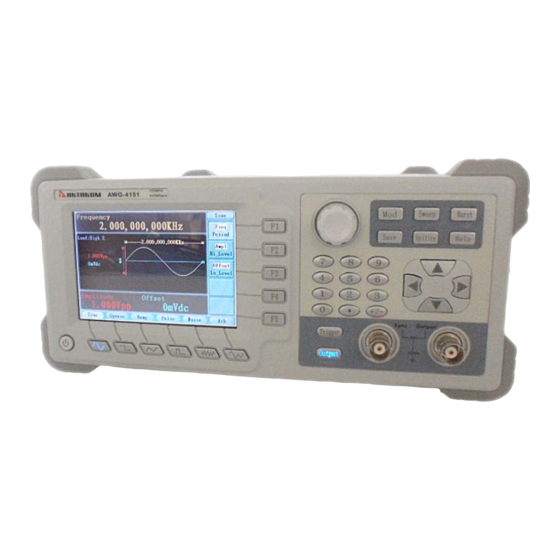
Front/Rear Panel and User Interface Front Panel Figure 4-1 Front panel overview ① LCD Display the user interface ② Menu selection Include 5 buttons: F1~F5 buttons ③ Knob Change the parameter Include 6 function keys: ④ Function area Mod : Generate the Modulated waveforms Sweep : Sweep Sine, Square or Ramp waveform Burst : Generate burst for Sine, Square, Ramp, Pulse and Arbitrary waveform... -
Page 9: Rear Panel
⑧ Trigger key Choose internal/external or manual Trigger ⑨ Output key Activate or deactivate the output signal ⑩ Number keys Input parameters, include: number, point and plus/minus sign Include: Sine, Square, Ramp, Pulse, Noise and Arbitrary ⑪ Waveform waveform selection buttons ⑫... -
Page 10: User Interface
such as connect a USB disk to the instrument. ⑪ USB Device port Connect as a “slave device” with an external USB device, such as connect the instrument to a PC. ⑫ Digital output User Interface ⑧ ① ② ③ ④... -
Page 11: Power-On Check
2. Check the Accessories The supplied accessories have been already described in the Appendix B “Accessories” of this Manual. You can check whether there is any loss of accessories with reference to this description Power-On Check AC Power Input Setting ADG-4151 adopt 110V/220V AC power source. -
Page 12: Front Panel Operation
5. Front Panel Operation This chapter will deal with the following topics mainly: How to Output Sine Signals How to Output Square Signals How to Output Ramp Signals How to Output Pulse Signals How to Output Noise Signals ... -
Page 13: To Set Signals
To set signals The following describes how to set and output Sine, Square, Ramp, Pulse, Noise and Arbitrary signals. To Output Sine Signals Press button to call the user interface of Sine signal, the Sine waveform parameters can be set by operating the Sine setting menu on the right. The parameters of Sine waveform are: Frequency/Period, Amplitude/High Level, Offset/Low Level. -
Page 14: To Set The Amplitude
Figure 5-2: Set the frequency using number keys To Set the Amplitude Press F2 , confirm whether the “Ampl” menu item is highlighted; if not, press F2 to switch into “Ampl”. In the Parameter bar 2, a cursor appears under the value of amplitude. Use the knob or the number keys to set the desired value. -
Page 15: To Set The Duty Cycle
Frequency Current parameter Current signal Parameter bar 1 Load Amplitude Setting menu of Offset Square signal Parameter bar 2 Duty cycle Figure 5-3: The User Interface of Square Signal Term Explanation Duty Cycle: The percentage that the High Level takes up the whole Period. To Set the Duty Cycle (1) Press F4 button, the “Duty”... -
Page 16: To Output Ramp Signals
To Output Ramp Signals Press button to call the user interface of Ramp signal, the Ramp waveform parameters can be set by operating the Ramp setting menu on the right. The parameters of Ramp waveform are: Frequency/Period, Amplitude/High Level, Offset/Low Level, Symmetry. You can operate the menu by using the menu selection buttons on the right. -
Page 17: To Output Pulse Signals
Symmetry Current parameter Parameter bar 1 Input box Symmetry Figure 5-6: Set the symmetry of Ramp signal To Output Pulse Signals Press button to call the user interface of Pulse signal, the Pulse waveform parameters can be set by operating the Pulse setting menu on the right. The parameters of Pulse waveform are: Frequency/Period, Amplitude/High Level, Offset/Low Level, Pulse Width/Duty, Edge Time. -
Page 18: To Set The Pulse Width / Duty Cycle
Term Explanation Pulse Width: There are two kinds of Pulse Width—positive and negative. Positive Pulse Width is the time span between thresholds of 50% of the rising edge amplitude to the next 50% of the falling edge amplitude. Negative Pulse Width is the time span between thresholds of 50% of the falling edge amplitude to the next 50% of the rising edge amplitude. -
Page 19: To Output Noise Signals
(2) Turn the knob to change the value directly; or press the number keys to input the desired value and choose the unit. The Edge Time range is 10nsec~40% of the Pulse Width. Edge time Current parameter Parameter bar 1 Input box Edge time Figure 5-9: Set the Edge Time of Pulse signal... -
Page 20: To Output Arbitrary Signals
To Output Arbitrary Signals Press button to call the user interface of Arbitrary signal, the Arbitrary waveform parameters can be set by operating the Arbitrary setting menu on the right. The parameters of Arbitrary waveform are: Frequency/Period, Amplitude/High Level, Offset/Low Level, Built-in Waveform. You can operate the menu by using the menu selection buttons on the right. -
Page 21: The User-Definable Waveform
Figure 5-12: The Exponential Fall Waveform Figure 5-13: The Sin(x)/x Waveform The User-Definable Waveform Press button and press F5 to select “Editable Wform”. Menu item Instruction Create Wform Create a new waveform. Select Wform Select the waveform stored in Flash memory. Edit Wform Edit the stored waveform. -
Page 22: To Generate The Modulated Waveform
(3) Set the interpolation: Press F2 to switch between On/Off. If you choose On, the points will be connected with beelines; otherwise, the voltages between two consecutive points will not change, and the waveform looks like a step-up one. (4) Edit the waveform points: Press F3 to enter the operation menu. Press F1 to choose “Points”, input the number of the point to be edited. - Page 23 Waveform varies with the instantaneous voltage of the modulating waveform. The user interface of the AM is shown as below. Current Parameter AM Frequency Load Modulating Waveform Mod Depth Carrier Waveform Mod Type Mod Shape Source Carrier Waveform Carrier Carrier Frequency Amplitude Figure 5-14: The User Interface of AM...
-
Page 24: Fm (Frequency Modulation)
Term Explanation AM Frequency: The frequency of modulating waveform. Mod Depth: The Amplitude Range of modulating waveform. In the 0% Modulation, the output amplitude is the half of the set one. In the 100% Modulation, the output amplitude is the same with the set one. For an external source, the depth of AM is controlled by the voltage level of the signal connected to the Modulation In connector in the rear panel. -
Page 25: Pm (Phase Modulation)
(6) Press F3 to set Mod Frequency. The range is 1μHz~20KHz (Internal source only). (7) Press F4 to set FM Deviation. The Deviation should be less than the Carrier Waveform Frequency. Note: The Sum of the Deviation and the Carrier Frequency should be equal to or less than maximum frequency of the selected function plus 1kHz. -
Page 26: Fsk (Frequency Shift Keying)
(4) Press F5 to select the source. If the source is External, use the Modulation In connector in the rear panel to input the external signal, then skip ahead to step (6). If you choose Internal, continue to the steps below. (5) Press F2 to choose Mod Shape, you can choose Sine, Square or Ramp. -
Page 27: Pwm (Pulse Width Modulation)
(4) Press F5 to select the source. If the source is External, use the Ext Trig/FSK/Burst connector in the rear panel to input the external signal, then skip ahead to step (5). If you choose Internal, continue to the steps below. (5) Press F3 to set FSK Rate. -
Page 28: To Generate Sweep
(4) Press F5 to select the source. If the source is External, use the Modulation In connector in the rear panel to input the external signal, then skip ahead to step (6). If you choose Internal, continue to the steps below. (5) Press F2 to choose Mod Shape, you can choose Sine, Square or Ramp. -
Page 29: To Generate Burst
parameters, please refer to “To set signals” on P10. Press button again to return to the Sweep mode interface. (3) Press F1 to set Sweep Time, the Time Span of the Sweep for which the Frequency changes from the Start Frequency to Stop Frequency. (4) Press F2 to select the Sweep Type. -
Page 30: Set The N-Cycle Burst
Set the N-Cycle Burst Burst Period Current Parameter Load Start Phase N Cycle Cycles Waveform Delay Source Waveform Figure 5-20: The User Interface of N-Cycle Burst (1) When the output signal is Sine, Square, Ramp, Pulse or Arbitrary waveform, press Burst function button to enter the Burst mode. -
Page 31: Set The Gated Burst
(9) Press F2 to select the source. Internal means using the internal source. External means using the Ext Trig/FSK/Burst connector in the rear panel to input the external signal. Manual means using the external source, set the start and stop time by hand. Set the Gated Burst Current Parameter Load... -
Page 32: To Edit The File Name
button to enter the file system, the storage menu will show “USBDEVICE” and “FLASH”. (2) Enter the storage: Press the ◄ / ► direction key to choose the desired storage. Press F1 to enter the chosen storage. (3) Remove the U disk: Remove the U disk from the USB Host port on the rear panel. The system will inform you “The USB device is removed”, and the “USBDEVICE”... -
Page 33: To Set The Separator
(2) Turn the knob to change the value; or press the number keys to input the desired value in percent, press F4 to select the unit. The bright range is 0%~100%. To Set the Separator The user can set the separator of the displayed parameter. (1) Press Utility and choose Disp Setup, press F2 to select Sep. -
Page 34: To Set The Sync Output
Note: AWG-4151 has a fixed 50Ω Series Impendence. No matter what Value the set parameter is, if the real load is different from the set one, the displayed voltage will not equal the real voltage. To Set the Sync Output The Generator provides Sync output through the Sync output terminal on the Front Panel. -
Page 35: To Set The Dc Output
For the Burst, when the burst starts, the Sync Signal is Level High. At the specific point when the Cycle Number ends, the Sync Signal turns Level Low (If the Waveform has a relative starting phase, it may be not zero intersections). For an infinite burst, the Sync Signal is the same with the Sync Signal of the continuous Signal. -
Page 36: To Set The System
Setting method: Turn the knob to change the value of cursor position in the Parameter bar. Press the ◄ / ► direction key to move the cursor. After setting, wait a few seconds (saving the parameters requires some time), and restart the waveform generator so that the new setting can be applied. - Page 37 (3) Press F3 to view the details about the topic; press F5 to go back to the catalog. (4) Press Help again to exit the help, or just do other operations.
-
Page 38: Communication With Pc
6. Communication with PC AWG-4151 Waveform Generator supports communications with a PC through USB, LAN or COM port. You can use the ultrawave communication software to set the parameters, control the output of the Waveform Generator, and synchronously display the screen of the Waveform Generator. - Page 39 (2) Set the network parameters of the computer. Since the Waveform Generator can not support obtaining an IP address automatically, you should assign a static IP address. Here we set the IP address to 192.168.1.71, Subnet mask is 255.255.255.0. Figure 6-2: Set the network parameters of the computer (3) Set the network parameters of the ultrawave software.
- Page 40 on P32. After restarting the Waveform Generator, if you can get data normally in the ultrawave software, the connection is successful. How to connect with the computer through a router: (1) Connection. Use a LAN cable to connect the Waveform Generator with a router, the LAN port of the Waveform Generator is in the rear panel;...
-
Page 41: Using Com Port
Figure 6-5: Set the network parameters of the ultrawave software (4) Set the network parameters of the Waveform Generator. In the Waveform Generator, press Utility and choose I/O Setup, press F2 to choose LAN, enter the submenu. Set the IP Addr and the Port to the same value as the “Ports-settings” in the software in step (3). -
Page 42: Troubleshooting
7. Troubleshooting 1. The instrument is powered on but no Display. Check whether the power connection is connected properly. Check if the Power Switch is in the proper voltage scale. Check whether the fuse which is below the AC Power socket is used appropriately and in good condition (the cover can be pried open with a straight screwdriver). -
Page 43: Technical Specifications
8. Technical Specifications All these specifications apply to the AWG Waveform Generator unless otherwise explanation. To reach these specifications, two conditions must be met first: The instrument must have been operating continuously for more than 30 minutes within the specified operating temperature. ... - Page 44 25 MHz to 150 MHz:<-30 dBc Total Harmonic Distortion (when 10 Hz to 20 kHz: <0.2 % the Amplitude is 1 Vp-p) Phase Noise (when the Amplitude is 20 MHz:<10 kHz offset 1 Vp-p) -110 dBc/Hz (typical) Residue Clock Noise -57 dBm (typical) Square Rise/Fall Time...
- Page 45 Carrier Waveforms Sine Source Internal/ External Internal Modulating Waveforms Sine, Square, Ramp, Noise, Arbitrary Internal Modulating Frequency 2 mHz to 20.00 kHz Phase Deviation 0°~180° Carrier Waveforms Sine Source Internal/ External Internal Modulating Waveforms 50% duty cycle square Internal Modulating Frequency 2 mHz to 1.000 MHz Carrier Waveforms Pulse...
- Page 46 Impedance 1 kΩ, AC coupled Requested Input voltage swing 100 mVp-p to 5 Vp-p locking range 20 MHz ± 35 kHz External Reference Clock Output Impedance 50 kΩ, AC coupled Amplitude 5 Vp-p, access 50Ω Trigger Output Level TTL-compatible Output Impedance 50Ω...
- Page 47 Display Display Type 3.9 inch colored LCD (Liquid Crystal Display) Display Resolution 480 (Horizontal) × 320 (Vertical) Pixels Display Colors 65536 colors, 8 bits, TFT screen Power Supply 100-240 VACRMS, 50/60Hz, CATⅡ Consumption Less than 50W 110V 125 V, F4AL Fuse 220V 250 V, F2AL...
-
Page 48: Appendix
9. Appendix Appendix A: Enclosure Standard Accessories: A power cord that fits the standard of the destination country A USB cable A CD (PC link application software) A User Manual A BNC/Q9 cable Appendix B: General Care and Cleaning General Care Do not store or leave the instrument where the liquid crystal display will be exposed to direct sunlight for long periods of time.
Need help?
Do you have a question about the AWG-4151 and is the answer not in the manual?
Questions and answers