
Subscribe to Our Youtube Channel
Related Manuals for Bredel 40-100


Summary of Contents for Bredel 40-100
- Page 1 Bredel 40-100 Operating Manual OHSAS 9001 14001 18001 Quality Environmental Occupational Management Management Health & Safety Management TYPE EL - CLASS I AUGUST 2012 m-bredel-40-100-en-05...
-
Page 2: Table Of Contents
4.3 Operation of the pump 4.4 Pump installation positions 4.5 Hose 4.6 Gearbox 4.7 Electric motor 4.8 Available options 5 Installation 5.1 Unpacking 5.2 Inspection 5.3 Installation conditions 5.4 Lifting and moving the pump 5.5 Placing the pump 6 Commissioning 6.1 Preparations m-bredel-40-100-en-05... - Page 3 8.9 Adjust the compression force (shimming) 8.10 Fitting options 9 Storage 9.1 Hose pump 9.2 Hose 9.3 Lubricant 10 Troubleshooting 11 Specifications 11.1 Pumphead 11.2 Lubricant for gearbox 11.3 Electric motor 11.4 Parts List 12 Appendix: Vacuum option 12.1 Description 12.2 Commissioning 12.3 Maintenance m-bredel-40-100-en-05...
- Page 4 12.4 Parts lists 13 Safety form m-bredel-40-100-en-05...
- Page 5 (electronically or mechanically) without the prior written authorisation of Watson-Marlow Bredel B.V.. Names, trade names, brands, etc. used by Watson-Marlow Bredel B.V. may not, as per the legislation concerning the protection of trade names, be considered as available.
- Page 6 Disclaimers The information contained in this document is believed to be correct but Watson-Marlow Bredel B.V. accepts no liability for any errors it contains and reserves the right to alter specifications without notice. The information provided can be changed without prior notification. Watson-Marlow Bredel B.V. or one of its representatives cannot be held liable for possible damage resulting from use of this manual.
- Page 7 For at se en oversættelse af vejledningen på dit sprog, scanne QR-koden. Suomi Saadaksesi käyttöoppaan omalla kielelläsi, skannaa QR-koodi. Norsk F or å lese håndboken oversatt til ditt eget språk, scan QRkoden. Svenska För att få en översättning av handboken på ditt språk, skanna QR-koden. m-bredel-40-100-en-05...
- Page 8 The following documents are available on the website: User manual in multiple languages Quick reference instructions for the replacement of the pump hose Note: The replacement instructions are only for users that are familiar with the replacement procedures in the user manual. m-bredel-40-100-en-05...
- Page 9 System requirements Source Hardware Software Internet browser Website PC or tablet PDF reader Internet browser QR code Smartphone or tablet with camera PDF reader App that can scan QR codes m-bredel-40-100-en-05...
- Page 10 1. Go to the website www.wmfts.com and select the 'Literature' tab. 2. Select Brand 'Bredel' and Document Type 'Manual' and then the required language. 3. Open or save the user manual. The PDF reader program shows the selected user manual.
- Page 11 Scan the QR code with your smartphone or tablet - The app forwards you to the webpage that contains the required language. 2. Open or save the user manual - The PDF reader program shows the selected user manual. m-bredel-40-100-en-05...
-
Page 12: General
How to use this manual This manual is intended as a reference book by means of which qualified users are able to install, commission and maintain the hose pumps Bredel 40, Bredel 50, Bredel 65, Bredel 80, and Bredel 100. Original instructions The original instructions for this manual have been written in English. -
Page 13: Environment And Disposal Of Waste
Neutralize residues of pumped liquid in the pump. • Dispose of the parts in accordance with local rules and regulations. Enquire within your local government about the possibilities for reuse or environment- friendly processing of packaging materials, (contaminated) lubricant, and oil. m-bredel-40-100-en-05... -
Page 14: Safety
Only use the pump in conformance with the intended use described above. The manufacturer cannot be held responsible for damage or harm resulting from use that is not in conformance with the intended use. If you want to change the application of your hose pump, contact your Bredel representative first. -
Page 15: Use In Potentially Explosive Atmospheres
A list of certified products and relevant chemicals can be found at http://www.nsf.org/certified- products-systems. For further details refer to the Bredel User Guide NSF 61 certified hose pumps supplied with such a pump, which can also be found on the website, or contact your Bredel representative for advice. -
Page 16: Qualification Of The User
Everyone who works with the hose pump must be aware of the contents of this manual and observe the instructions with great care. • Never change the order of the actions to be carried out. • Always store the manual near the hose pump. m-bredel-40-100-en-05... -
Page 17: Warranty Conditions
Warranties purporting to be on behalf of Bredel made by any person, including representatives of Bredel, its subsidiaries, or its distributors, which do not accord with the terms of this warranty shall not be binding upon Bredel unless expressly approved in writing by a Director or Manager of Bredel. -
Page 18: Description
Frequency controller (option) Electric motor Identification of the pump The identification plate on the pumphead contains the following data: YEAR: Watson-Marlow Bredel B.V. Sluisstraat 7-Delden-NL www.bredel.com Patent applied Type number Serial number ATEX code, if applicable ATEX document number Year of manufacture ... - Page 19 B Type number (Type/ Output) E Input (adaptation of the motor to the gearbox) C Reduction (i=) Bredel part or order number (PN) Identification of the electric motor The identification plate on the electric motor contains the following data: Overview Bredel part number, starting with "28-..."...
- Page 20 OEM identification plate for electric motors up to 7.5 kW (IEC frame size 132) IE3-91.2% 03FEV10 0000000000 ME95 Serial number Frequency Type number Speed Power Insulation class Voltage Protection class m-bredel-40-100-en-05...
- Page 21 High precision pump element machined for element machined for element machined for Pump type Remarks, if applicable Part number Maximum permissible working pressure Internal diameter G Production code D Type of material of inner liner H Hose type, transfer or metering m-bredel-40-100-en-05...
-
Page 22: Construction Of The Pump
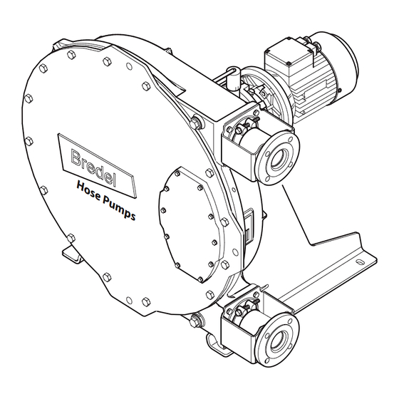
Construction of the pump Hose Inspection window Pump housing Supports Rotor Gearbox Pressing shoes Electric motor Cover m-bredel-40-100-en-05... -
Page 23: Operation Of The Pump
When the first pressing shoe leaves the pump hose, the second pressing shoe has already occluded the hose and fluid is prevented from flowing back. This method of liquid displacement is known as the "positive displacement principle". m-bredel-40-100-en-05... -
Page 24: Pump Installation Positions
Pump ports facing upwards. Pump ports facing downwards. Concerning pumps Bredel 40, Bredel 50, Bredel 65, Bredel 80, and Bredel 100 the inspection window always resides between the inlet and the outlet port. An accurate reading of the lubricant level through the inspection window is only possible at pump positions 1 and 2. -
Page 25: Hose
NBR for food* Nitrile rubber Yellow F-NBR for food (white inner liner)* Nitrile rubber Yellow EPDM EPDM Blue *See also Dedicated manuals: NBR hoses for food contact, part number 28-29211330 F-NBR hoses for food contact, part number 28-29211322 m-bredel-40-100-en-05... - Page 26 Note: Contact your Bredel representative for advice about the chemical and temperature resistance of the hoses. The Bredel hoses are carefully manufactured and quality checked to achieve minimum tolerances in wall thickness. It is very important to guarantee the correct compression of the hose, because: •...
-
Page 27: Gearbox
Note: Consult your Bredel representative for advice on lubrication when operating the hose pump below 2 rpm. Gearbox The hose pump types described in this manual use planetary gearbox units. The gearbox units are characterized by their compact and modular construction. This modular construction enables a wide range of reductions, torques and connection possibilities for the electric motor. -
Page 28: Available Options
Heavy duty bearings • Special configuration for use in potentially explosive atmospheres The high level float switch is mandatory for use in potentially explosive atmospheres. If the pump is to be used in potentially explosive atmospheres, contact your Bredel representative. m-bredel-40-100-en-05... -
Page 29: Installation
Inspection Check that all components are present. Inspect components for damage in transit. If anything is missing or damaged, contact your distributor immediately. Report any damage immediately to your Bredel representative. Installation conditions Ambient conditions Make sure that the hose pump is in an area where the ambient temperature during operation is not lower than -20 °C and not higher than +45 °C. - Page 30 A segment of three quarters (3/4) of the pump hose length for the flexible pipe work is recommended. Bredel also recommends installing an isolation valve and pipedrain in the suction and discharge pipework to allow fluid isolation and drainage from the pump during maintenance.
- Page 31 For connecting PTC thermistors (if present) a special thermistor relay must be used. In case of doubt, contact your Bredel representative for advice. Refer to the documentation supplied with the electric motor for information on how to connect the motor to your power supply.
-
Page 32: Lifting And Moving The Pump
The maximum rating of the lifting point depends on the pump model. Make sure that the total of weight to be moved will not exceed this maximum rating. Maximum rating of the lifting point of the pumphead Bredel 40 Bredel 50 Bredel 65... -
Page 33: Placing The Pump
In case of fixing to the floor use holes (A) or (B) and holes (C) at both sides of the pump. • In case of levelling elements, use holes (A) and holes (C) at both sides of the pump. Note: If the pump installation position is in position 4, then the use of levelling elements is not possible. m-bredel-40-100-en-05... - Page 34 Unit Bredel 40 Bredel 50 Flange thickness (d Bredel 65 Bredel 80 Bredel 100 Bredel 40 - Bredel 65 18 x 30 Flange hole diameter Bredel 80 - Bredel 100 22 x 45 Bredel 40 - Bredel 65 28-F550041 Bredel part no.
- Page 35 Item Pump Specification Unit Bredel 40 - Bredel 65 Anchor bolt length (l) Bredel 80 - Bredel 100 Bredel 40 - Bredel 65 Minimum foundation height (d) Bredel 80 - Bredel 100 Bredel 40 - Bredel 65 Drill diameter Bredel 80 - Bredel 100...
- Page 36 Installing the cover lifting device (CLD) The cover lifting device is available for Bredel 50, Bredel 65, Bredel 80 and Bredel 100 only. It is applicable for pump positions 1 and 2 only. See also Refer to "Pump installation positions" on page 24...
- Page 37 Boom fixation bolt C1 C2 Place the threaded rod (A) in the correct hole in the boom (B). For Bredel 50 apply hole C1, for Bredel 65 hole C2 and for Bredel 80 and 100 hole C3. Place rings and nut (D) on the rod (A).
-
Page 38: Commissioning
Check that the lubricant level is above the minimum level line in the inspection window. If necessary refill with Bredel Genuine Hose Lubricant via the breather plug. Check that the correct number of shims corresponds with your application. -
Page 39: Commissioning
Check the capacity of the hose pump. If the capacity differs from your specification, follow the instructions in Troubleshooting or contact your Bredel representative for advice. If a frequency controller is present, check the capacity range. In case of any deviations consult the supplier’s documentation. -
Page 40: Operation
45 °C. If the duty for an application is specified in the area of intermittent operation, let the pump stand still to cool down for at least one hour after three hours of operation. m-bredel-40-100-en-05... - Page 41 Start at the product temperature (D) Meet the line of the required discharge pressure (E). Read the maximum allowed pump speed (F). Note: Pump stroke volume is based on new hoses and flooded suction. Actual stroke volume may vary. m-bredel-40-100-en-05...
- Page 42 Performance graph Bredel 40 Bredel 40 Required motor power in kW (HP) 3.0 (4.02) Product temperature °C (°F) 2.5 (3.35) 2.0 (2.68) 40 (104) Intermittent Duty 50 (122) 100 kPa = 1 bar 1.5 (2.01) 60 (140) Continuous Duty 1.0 (1.34)
- Page 43 Performance graph Bredel 65 Bredel 65 Required motor power in kW (HP) Product temperature °C (°F) 40 (104) Intermittent Duty 50 (122) 100 kPa = 1 bar 60 (140) Continuous Duty 70 (158) 80 (176) Pump speed [rpm] 8000 12000...
-
Page 44: Dry Running
Capacity per revolution: 20.0 l/rev Dry running Dry running is a running condition of the pump when no fluid is flowing through the hose. Bredel hose pumps allow dry running for limited periods. Dry running imposes an additional thermal load on the hose, because a part of the internal heat associated with repetitive hose compression is normally removed by the process fluid. -
Page 45: Hose Failure
Consequences of a hose failure In general, this will not cause a hazardous situation because the Bredel Genuine Hose Lubricant is harmless (approved by the United States Food and Drug Administration). However, there is an exception in case of pumping a strong oxidiser or a strong acid. - Page 46 Note: Regularly replace the hose to avoid hose failure and additional downtime. Hose life depends on the operating condition, process fluid and hose material. The end-user should be aware of this and establish the frequency of preventive hose replacement. In case of doubt, consult your Bredel representative.
-
Page 47: Fluid Leakage
To avoid consequential damage, the pump must be stopped and lubricant levels of the pumphead and gearbox must be checked. The damaged seal should be replaced. WARNING Risk of injury from falling! Process fluid mixed with pump lubricant that is leaking from the pump can make floors slippery. m-bredel-40-100-en-05... -
Page 48: Maintenance
Check that all components are present. Inspect components for damage in transit. If anything is missing or damaged, contact your distributor immediately. Note: Do not install damaged parts. If in doubt, contact your Bredel representative for advice. Maintenance and periodic inspections The following maintenance schedule shows the maintenance and periodic inspection that need to be carried out on the hose pump to guarantee optimal safety, operation and life of the pump. - Page 49 Check that the lubricant level is above the minimum level line in the inspection Before start-up of the window. If necessary refill Check the lubricant pump and at scheduled with Bredel Genuine Hose level. intervals during Lubricant via the breather operation. plug.
-
Page 50: Additional Maintenance In Potentially Explosive Environments
Replace the According to ATEX regulations after 20,000 hrs. Refer to "Exchanging bearings. service or when damage is suspected. replacement parts" on page 65 Clean the In potentially explosive (dust) atmospheres, the hose pump. dust must be removed regularly. m-bredel-40-100-en-05... -
Page 51: Cleaning The Hose
Refer to the documentation of the cleaning products and the hose for more information. A proper result of a cleaning process in this way is not guaranteed by Bredel , while it strongly depends on the type of pumped fluid and the cleaning fluid applied. -
Page 52: Changing Lubricant
For this purpose remove the breather cap (B) and position a funnel (C) in the breather. In order to facilitate the filling with lubricant the plug (D) on the front of the pump housing can be removed. Pour the lubricant into the pump housing through the funnel. m-bredel-40-100-en-05... -
Page 53: Changing Oil In The Gearbox
Remove the level plug (B) and breather (C). Position a funnel in the hole of breather (C) and fill the gearbox with oil until the oil just comes out of the level plug hole (B). Place level plug (B) and breather (C) back and tighten them firmly. m-bredel-40-100-en-05... -
Page 54: Changing The Hose
Collect the lubricant from the pump housing in the tray. Check the sealing ring (C) is not damaged and replace it if necessary. Check that the breather vent mounted on the rear is not obscured. Position the drain plug and tighten it to the specified torque. m-bredel-40-100-en-05... - Page 55 Loosen the hose clamp (A) of both the inlet and outlet ports by loosening the retaining bolt (B). Pull the insert (B) from the hose and remove the flanges (A). Carry out this procedure both for the inlet and outlet ports. m-bredel-40-100-en-05...
- Page 56 Slide off the sealing ring (A). Check that the sealing ring is not deformed or damaged and replace it if necessary. Carry out this procedure both for the inlet and outlet ports. Connect the pump to the electrical supply. Switch on the electrical supply. m-bredel-40-100-en-05...
- Page 57 Isolate the pump from the electrical supply. CAUTION Never dismount the cover, when the pump hose is in the pumphead. The compression forces on the pump hose are partially compensated by the cover. By removing the cover, the pump housing may become deformed. m-bredel-40-100-en-05...
- Page 58 When the pressing shoes are worn the compression force of the hose decreases. If the compression force is too low, this results in a loss of capacity by the backflow of the liquid to be pumped. Backflow results in a reduction of the life of the hose. m-bredel-40-100-en-05...
- Page 59 Connect the pump to the electrical supply. Switch on the electrical supply. Fitting the hose Clean the (new) hose on the outside and fully lubricate the outside with Bredel Genuine Hose Lubricant. Fit the hose (A) via one of the ports.
- Page 60 Position the retaining bolts (A) and tighten them until they are approx. 5 mm from the port, so that the gap between the flange bracket and the port remains. m-bredel-40-100-en-05...
- Page 61 Slide insert (B) in flange (A) and press the insert in the hose. If necessary lubricate the insert with Bredel Genuine Hose Lubricant in order to simplify mounting. Make sure that the holes in flange (A) are aligned with the holes in flange bracket (C). Check that the insert is in the correct place.
- Page 62 Now fit the other port. For this port proceed in the same way as described above for the inlet port. Fill the pump housing with Bredel Genuine Hose Lubricant. Connect the suction and discharge lines (B). Position the retaining bolts (A) and tighten them to the specified torque.
- Page 63 How to tighten hose clamps in combination with plastic inserts Bredel pumps are supplied with one clamp per hose end as standard. The clamp is positioned close to the pump side to assure a sanitary connection between hose and insert. In case of plastic inserts, the amount of clamping must be limited to avoid deformation of the plastic insert which would lead to leakage instead.
- Page 64 Left: Standard arrangement with one hose clamp near the pump housing. For low pressure demand. Centre: Alternative arrangement with two hose clamps. For high pressure and sanitary demand. Right: Alternative arrangement with one hose clamp near the flange. Only for high pressure demand. m-bredel-40-100-en-05...
-
Page 65: Exchanging Replacement Parts
Remove the drain plug (B). Collect the lubricant from the pump housing in the tray. Drain as much Bredel Genuine Hose Lubricant until the level has lowered just below the inspection window (D). - Page 66 Loosen the retaining bolt (s) (A) of pressing shoe (B) completely and remove the pressing shoe. Position the (new) pressing shoe (A), check that the NordLock®-rings (B) have been positioned correctly and tighten the retaining bolt(s) a few turns. m-bredel-40-100-en-05...
- Page 67 Refit the inspection window (B). Make sure that all retaining bolts (A) are refitted and that they are tightened in the correct order, diagonally opposite each other. Tighten the bolts with the specified torque. Refill the lubricant. Connect the pump to the electrical supply. Switch on the electrical supply. m-bredel-40-100-en-05...
- Page 68 Remove the retaining bolts (A) of the drive shaft (B) and remove the drive shaft. Note: If the drive shaft cannot be removed manually, use a screwdriver in the slots in the rotor provided for this purpose. Check the sealing ring (C) is not damaged and replace it if necessary. m-bredel-40-100-en-05...
- Page 69 A suitable puller or similar extraction tool will be required during this stage of the disassembly. When removing the rotor a belt or similar lifting aid must carry the weight of the rotor. For the specific weight of the rotor: Refer to "Weights" on page 95 m-bredel-40-100-en-05...
- Page 70 Support the rotor with wooden blocks at 90° to the spokes, with the wear ring (A) facing down. Position a suitable punch against the rear of the glued wear ring. Prevent damage to the wear ring seat or other parts. m-bredel-40-100-en-05...
- Page 71 Fit the rotor (A).The bearings have been placed on the hub with a slight interference fit. Use a pressing tool to press the rotor on the hub. Check rotor retaining circlip (A) for any signs of damage and replace if necessary. Mount the retaining circlip (A). Use the correct tools for this purpose. m-bredel-40-100-en-05...
- Page 72 Refit the cover. Make sure that the bolts are refitted and that they are tightened in the correct order, diagonally opposite each other. Connect the pump to the electrical supply. Switch on the electrical supply. Fit the (new) pump hose. See also Refer to "Fitting the hose" on page 59 m-bredel-40-100-en-05...
- Page 73 Note: The rotor retaining circlip (A) locks the rotor on the hub. Turn the rotor over. Remove the bearing (A), the spacer ring (B) and the bearing (C) with the correct tool. Check the spacer ring (B) for damage and replace it if necessary. Retain the spacer ring (B). m-bredel-40-100-en-05...
- Page 74 Check rotor retaining circlip (A) for any signs of damage and replace if necessary. Mount the retaining circlip (A). Use the correct tools for this purpose. Fit the rotor, the cover and pump hose See also Refer to "Changing the hose" on page 54 m-bredel-40-100-en-05...
-
Page 75: Adjust The Compression Force (Shimming)
Jog the motor until the pressing shoe (B) is positioned in view of the inspection window (A). Isolate the pump from the electrical supply. Note: The drain plug is in the bottom of the pumphead. m-bredel-40-100-en-05... - Page 76 Remove the drain plug (E). Collect the lubricant from the pump housing in the tray. Drain as much Bredel Genuine Hose Lubricant until the level has lowered just below the inspection window (D).
- Page 77 Isolate the pump from the electrical supply. Repeat the procedure for this second pressing shoe. Refill the lubricant. See also Refer to "Changing lubricant" on page 52 Refer to "Torque figures" on page 95 Refer to "Shims specifications" on page 96 m-bredel-40-100-en-05...
-
Page 78: Fitting Options
8.10 Fitting options Fitting a high level float switch For explosive environments, contact your Bredel representative. Dismount the standard breather (A) rear of the pump, by dismounting it from the crimp connector (B). Slide the standard breather cap (A) from the breather (B). - Page 79 (2 x 0.34 mm ). Bear in mind that the electrical contact of the float switch is normally closed (NC). The knob is upwards for normally closed operation. When the lubricant level is (too) high the contact will open. m-bredel-40-100-en-05...
- Page 80 Check if the float switch is mounted with the NC sign at the top. Fitting a low-level float switch For explosive environments, contact your Bredel representative. m-bredel-40-100-en-05...
- Page 81 (NC). When the lubricant level is (too) low the contact will open. Refill the lubricant. Breathe the float switch by carefully opening the plug (C) until lubricant escapes. Subsequently close the plug again. See also Refer to "Fitting a high level float switch" on page 1 m-bredel-40-100-en-05...
- Page 82 Replace pressing shoe by the special pressing shoe with a magnet (A). See also Refer to "Replacing the pressing shoes" on page 65 Note: Make sure that the pressing shoe is placed in such a way that the magnet (A) is at the backside and facing the pump housing. m-bredel-40-100-en-05...
- Page 83 Fit the inductive sensor (A) in plug (B) and adjust it to dimension "X" as indicated in the table below. Use sealant Loctite 572 or similar to prevent leakage. Pump type Dimension “X” Bredel 40 32 +0 /-1 Bredel 50 32 +0 /-1...
- Page 84 Connect the sensor via the 2- meter long PVC cable (3 x 0.34 mm Specifications Voltage 10-30 VDC Current Max. 150 mA WARNING Contact your Bredel representative for proper connection of the sensor. For explosive environments, contact your Bredel representative. m-bredel-40-100-en-05...
-
Page 85: Storage
Replace the pump lubricant in case of failure of the pump hose and in any case after one year. • Use the lubricant before the best-before date marked on the container. • The lubricant must be stored in closed bottles or cans to avoid absorption of moisture. m-bredel-40-100-en-05... -
Page 86: Troubleshooting
If the hose pump does not function (correctly), consult the following check list to see if you can remedy the error yourself. If you cannot, contact your Bredel representative for advice. Problem Possible cause... - Page 87 Problem Possible cause Correction In case of doubt, consult your Non-standard hose lubricant used. Bredel representative. Add Bredel Genuine Hose Lubricant. For the required amount of lubricant Low lubricant level. Refer to "Lubricant table pump" on page 94 Check the performance graph.
- Page 88 In case pipework. combination of these factors. of doubt, consult your Bredel representative. Too narrow diameter of suction and/or Increase the diameter of the discharge line.
- Page 89 Insufficient or no hose lubricant in the Add extra lubricant. Refer to pumphead. "Changing lubricant" on page 52. Incorrect lubricant: no Bredel Genuine Hose In case of doubt, consult your Lubricant in the pumphead. Bredel representative. Extremely high inlet pressure - larger than Reduce the inlet pressure.
- Page 90 Replace the insert if Plastic insert: the hose clamp is tightened hose and the necessary. too much and as a result the insert is insert. deformed. Refer to "Tightening the hose clamps" on page 62 m-bredel-40-100-en-05...
- Page 91 Inspect the O-ring and replace it if Lubricant necessary. Lubricate the O-ring The O-ring in the bracket is damaged, or not leakage before installation with Bredel correctly positioned in the bracket. between the Genuine Hose Lubricant. Refer to pump housing "Fitting the hose"...
-
Page 92: Specifications
Permissible ambient temperature -20 to +45 [°C] Permissible product temperature -10 to +80 [°C] Sound level at 1 m [dB(A)] * Intermittent duty: Let the pump stand still to cool down for at least one hour after two hours of operation. m-bredel-40-100-en-05... - Page 93 Commercial grade mild steel 37 Pump rotor Cast-iron Pressing shoes Aluminium (Epoxy is optional) Supports Mild steel, galvanized* Hose flange brackets Mild steel, galvanized* Cover fixings Mild steel, galvanized* Motor fixings Mild steel, galvanized* Mounting material of supports Mild steel, galvanized* m-bredel-40-100-en-05...
- Page 94 Lubricant Bredel* Bredel* Bredel* Bredel* Bredel* Required quantity (l) Bredel Genuine Hose Lubricant is registered at NSF: NSF Registration No 123204; Category Code H1. Also refer to: www.nsf.org/certified-products-systems, and search for 'Bredel'. Components Glycerol 50-100% w/w Glycol 2.5-10% w/w Water ...
- Page 95 Weights Weight [kg] Description Bredel 40 Bredel 50 Bredel 65 Bredel 80 Bredel 100 Hose pump, maximum weight* 1300 Pumphead** 1032 Rotor Pressing shoe 12.6 Pump cover 62.5 106.5 Drive shaft 16.6 19.5 Hose 11.5 * Maximum net weight of the hose pump with the heaviest gearbox and electric motor.
- Page 96 Note: All bolts are class 8.8. Shims specifications How to use the diagrams: Note: Specifications only valid for genuine Bredel hoses. Find the pump speed in [rpm] on the horizontal axis. Go straight up and meet the proper discharge-pressure line.
- Page 97 • When the product temperatures are above 60 °C always use one shim less than indicated in the diagrams. • Each diagram gives the number of shims per pressing shoe. • Shim both pressing shoes identically. m-bredel-40-100-en-05...
- Page 98 Bredel 40 - NR Metering hose Bredel 50 - NR Metering hose Bredel 80 - NR Metering hose Bredel 65 - NR Metering hose Bredel 100 - NR Metering hose X = Pump speed Y = Number of shims per shoe ...
- Page 99 Bredel 40 NR - Transfer Hose Bredel 50 NR - Transfer Hose Bredel 80 NR - Transfer Hose Bredel 65 NR - Transfer Hose Bredel 100 NR - Transfer Hose X = Pump speed Y = Number of shims per shoe...
-
Page 100: Lubricant For Gearbox
For the food industry as well as for agricultural areas and nature reserves, special grade lubricants are available. The table below is an indication for proper viscosity values. If you have any questions, contact your Bredel representative for advice. Recommended lubricant parameters for the Bredel gearboxes Mineral Oil... -
Page 101: Parts List
Rotor assembly.Refer to "Rotor assembly." on page 105 Pump housing assembly. Refer to "Pump housing assembly." on page 109 Pump support assembly. Refer to "Pump support assembly." on page 115 Flange assembly. Refer to "Flange assembly." on page 117 Lubricant. Refer to "Lubricant." on page 123 m-bredel-40-100-en-05... - Page 102 Cover assembly. Bredel 40 Pos. Qty. Description Product code Sticker 28-240238 Bolt, hex. head 28-F111042 Washer, plain 28-F322009 Inspection window 28-240155 Gasket 28-240156 Bolt, hex. head 28-F111096 Washer, plain 28-F322013 Pump cover 28-240102 Seal ring (quad ring) 28-240123 m-bredel-40-100-en-05...
- Page 103 Bredel 50 Pos. Qty. Description Product code Sticker 28-250238 Bolt, hex. head 28-F111074 Washer, plain 28-F322012 Inspection window 28-250155 Gasket 28-250156 Bolt, hex. head 28-F111130 Washer, plain 28-F322015 Pump cover 28-250102 Seal ring (quad ring) 28-250123 Bredel 65 Pos. Qty.
- Page 104 Bredel 80 Pos. Qty. Description Product code Sticker 28-280238 Bolt, hex. head 28-F101038 Washer, plain 28-F322012 Inspection window 28-280155 Gasket 28-280156 Bolt, hex. head 28-F111182 Washer, plain 28-F322017 Pump cover 28-280102 Seal ring (quad ring) 28-280123 Bredel 100 Pos. Qty.
- Page 105 Rotor assembly. Bredel 40 Pos. Qty. Description Product code Bolt, hex. head 28-F111073 Washer, spring Lock 28-F336011 Drive shaft 28-240104 O-ring 28-S122431 Bolt, hex. head 28-F101059 Nord-Lock® ring 28-F349005 Rotor 28-240103 Shim 28-240107 Pressing shoe: aluminium 28-240110 Epoxy, with stainless steel insert...
- Page 106 Pos. Qty. Description Product code Bearing 28-B141460 Spacer outside 28-29110201 Retaining ring 28-F344077 Wear ring 28-29140202 Bredel 50 Pos. Qty. Description Product code Bolt, hex. head 28-F111098 Washer, spring Lock 28-F336012 Drive shaft 28-250104 O-ring 28-S122541 Bolt, hex. head 28-F101082 Nord-Lock®...
- Page 107 28-B142060 Spacer outside 28-29151201 Retaining ring 28-F344087 Wear ring 28-29180202 * For the drive shaft of the heavy duty drive (gearboxes 28- G0217… and 28-G0218…), consult your Bredel representative. Bredel 80 Pos. Qty. Description Product code Bolt, hex. head 28-F111184...
- Page 108 28-B142460 Spacer outside 28-29180201 Retaining ring 28-F344093 Wear ring 28-29240202 * For the drive shaft of the heavy duty drive (gearboxes 28- G0224… and 28-G0225…), consult your Bredel representative. Bredel 100 Pos. Qty. Description Product code Bolt, hex. head 28-F111184...
- Page 109 Pos. Qty. Description Product code Bearing 28-B142460 Spacer outside 28-29181201 Retaining ring 28-F344093 Wear ring 28-29240202 Pump housing assembly. Bredel 40 Pos. Qty. Description Product code Pump housing 28-240101 Packing ring 28-29040257 Plug, int. hex. hd 28-F901006 Breather cap 28-29065223...
- Page 110 Hose NBR Food 28-040061 Hose F-NBR 28-040065 EPDM 28-040075 28-040070 Washer 28-F332005 Bolt, hex. socket cap head 28-F201064 Bredel 50 Pos. Qty. Description Product code Pump housing 28-250101 Packing ring 28-29040257 Plug, int. hex. hd 28-F901006 Breather cap 28-29065223...
- Page 111 28-1000065 28-050040 Hose NBR Food 28-050061 Hose F-NBR 28-050065 EPDM 28-050075 28-050070 Washer 28-F332007 Bolt, hex. socket cap head 28-F201106 Bredel 65 Pos. Qty. Description Product code Pump housing 28-265101 Packing ring 28-29040257 Plug, int. hex. hd 28-F901006 m-bredel-40-100-en-05...
- Page 112 Hose F-NBR 28-065065 EPDM 28-065075 28-065070 Washer* 28-F332007 Bolt, hex. socket cap head* 28-F201106 * For fixation of the heavy duty drive (gearboxes 28-G0217... and 28-G0218...), consult your Bredel representative. Bredel 80 Pos. Qty. Description Product code Pump housing 28-280101...
- Page 113 NR Metering hose 28-080020 28-080040 Hose NBR Food 28-080061 Hose F-NBR 28-080065 EPDM 28-080075 28-080070 Washer* 28-F332007 Bolt, hex. socket cap head* 28-F201106 * For fixation of the heavy duty drive (gearboxes 28-G0224... and 28-G0225...), consult your Bredel representative. m-bredel-40-100-en-05...
- Page 114 Bredel 100 Pos. Qty. Description Product code Pump housing 28-200101 Packing ring 28-29056244 Plug, int. hex. hd 28-F901008 Breather cap 28-29089223 Breather 28-29125146 Coupling, straight 28-F602008 Plug, ext. hex. hd. 28-F911008 O-ring 28-S122801 Dowel pin 28-F416121 28-200203 Washer, spring Lock 28-F336015 Bolt, hex.
- Page 115 Pump support assembly. Bredel 40 Pos. Qty. Description Product code Support, right 28-240106B Support, left 28-240106A Washer, spring Lock 28-F336012 Bolt, hex. head 28-F111096 Bredel 50 Pos. Qty. Description Product code Support, right 28-250106B Support, left 28-250106A Washer, spring Lock 28-F336012 Bolt, hex.
- Page 116 Bredel 65 Pos. Qty. Description Product code Support, right 28-265106B Support, left 28-265106A Washer, spring Lock 28-F336013 Bolt, hex. head 28-F111132 Bredel 80 Pos. Qty. Description Product code Support, right 28-280106B Support, left 28-280106A Washer, spring Lock 28-F336015 Bolt, hex. head...
- Page 117 Flange assembly. Bredel 40 Pos. Qty. Description Product code O-ring 28-S112301 Flange bracket, EN/JIS Steel 28-240197 Flange bracket, EN/JIS SS 28-240197E Flange bracket, ANSI Steel 28-240197A Flange bracket, ANSI SS 28-240197F Washer, spring Lock 28-F336011 Bolt, hex. head 28-F111071 Hose clamp...
- Page 118 28-040198A Flange, ANSI SS 28-240199A Insert, AISI 316 28-040186 Insert, PP 28-240189 Insert, PVC 28-240187 Insert, PVDF 28-240190 Bredel 50 Pos. Qty. Description Product code O-ring 28-S112371 Flange bracket, EN/ANSI/JIS Steel 28-250197 Flange bracket, EN/ANSI/JIS SS 28-250197E Washer, spring Lock 28-F336012 Bolt, hex.
- Page 119 Qty. Description Product code Insert, AISI 316 28-050186 Insert, PP 28-240189 Insert, PVC 28-250187 Insert, PVDF 28-250190 Bredel 65 Pos. Qty. Description Product code O-ring 28-S112431 Flange bracket, EN/ANSI/JIS Steel 28-265197 Flange bracket, EN/ANSI/JIS SS 28-265197E Flange bracket, DIN ANSI Steel...
- Page 120 Bredel 80 Pos. Qty. Description Product code O-ring 28-S112501 Flange bracket, EN/JIS Steel 28-280197 Flange bracket, EN/JIS SS 28-280197E Flange bracket, ANSI Steel 28-280197A Flange bracket, ANSI SS 28-280197F Washer, spring Lock 28-F336013 Bolt, hex. head 28-F111128 Hose clamp 28-C101051...
- Page 121 Bolt, hex. head 28-F111130 Hose clamp 28-C101054 Flange, DIN Steel 28-100198 Flange, DIN SS 28-200199 Flange, ANSI Steel 28-100198A Flange, ANSI SS 28-200199A Insert, AISI 316 28-200186 Insert, PP 28-200189 Insert, PVC 28-200187 Insert, PVDF 28-200190 Revolution counter assembly m-bredel-40-100-en-05...
- Page 122 Bredel 40 Pos. Qty. Description Product code Gasket 28-29040257 Revolution counter 28-29040462 Adapter 28-29039460 Bredel 50 Pos. Qty. Description Product code Gasket 28-29040257 Revolution counter 28-29040462 Adapter 28-29039460 Bredel 65 Pos. Qty. Description Product code Gasket 28-29040257 Revolution counter 28-29040462...
- Page 123 Lubricant. Bredel 40 Pos. Qty. Description Product code 5 l can Bredel Genuine Hose Lubricant 28-903143 Bredel 50 Pos. Qty. Description Product code 10 l can Bredel Genuine Hose Lubricant 28-904143 Bredel 65 Pos. Qty. Description Product code 20 l can Bredel Genuine Hose Lubricant...
-
Page 124: Appendix: Vacuum Option
The pressure of the pumphead can be adjusted with the reducer valve. 12.2 Commissioning Commissioning a pump that has the pneumatic vacuum unit option Do the general commissioning of the pump. Turn the knob of the reducer valve (A) to close the reducer valve. m-bredel-40-100-en-05... -
Page 125: Maintenance
Remove the circlip (A) next to the seal from the hub (B) by pressing the pin shaped tooling on the slanting end (C). The circlip end will rise out of the groove. By moving the tooling along the circumference, the whole circlip can be loosened. m-bredel-40-100-en-05... - Page 126 (D). CAUTION The seal lips have a different hardness. Be sure to mount the seal with the side with the name “BREDEL” pointing toward the pump cover. Mount the retaining circlip (A). Use the correct tools for this purpose. m-bredel-40-100-en-05...
- Page 127 Folding back of the seal lip may lead to fatal damage of the seal. If the seal lip is folded back, repair this by carefully turning or moving back the rotor. 12.4 Parts lists Indicated quantities are per pumphead. (except for pos. 7. Base set: 1 per pump) m-bredel-40-100-en-05...
- Page 128 Bredel 40 Pos. Qty. Description Product code Retaining ring 28-F346098 Seal ring 28-S222811 Breather 28-29133146 Elbow coupling 28-AL38890813 Breather cap 28-29088223 Breather cap with high level switch 28-29106610 Washer (PA6) 28-F724004 Base set 28-29180292 m-bredel-40-100-en-05...
- Page 129 Bredel 50 Pos. Qty. Description Product code Retaining ring 28-F346107 Seal ring 28-S223611 Breather 28-29133146 Elbow coupling 28-AL38890813 Breather cap 28-29088223 Breather cap with high level switch 28-29106610 Washer (PA6) 28-F724006 Base set 28-29180292 Bredel 65 Pos. Qty. Description Product code...
- Page 130 Bredel 80 Pos. Qty. Description Product code Retaining ring 28-F346115 Seal ring 28-S224811 Breather 28-29210146 Elbow coupling 28-AL38890813 Breather cap 28-29089223 Breather cap with high level switch 28-29124610 Washer (PA6) 28-F724006 Base set 28-29180292 Bredel 100 Pos. Qty. Description Product code...
- Page 131 Bredel hose pump series Type designation: Bredel 40, Bredel 50, Bredel 65, Bredel 80, Bredel 100 This declaration of conformity is issued under the sole responsibility of the manufacturer. The object of the declaration described above is in conformity with the relevant harmonisation...
- Page 132 In compliance with the Health and Safety Regulations, the user is required to declare those substances that have been in contact with the item(s) you are returning to Watson-Marlow Bredel B.V. or any of its subsidiaries or distributors. Failure to do so will cause delays in servicing the item or in issuing a response.
Need help?
Do you have a question about the 40-100 and is the answer not in the manual?
Questions and answers