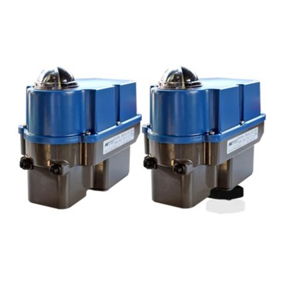
Summary of Contents for PS Automation PSF-Q-M Series
- Page 1 PSF-Q-M Operating Instructions Version 2023/09/26 Art.No.: 8035615 ©2023 PS Automation GmbH Subject to changes...
-
Page 2: Table Of Contents
Contents Type key .................................... 2 1. Symbols and safety ............................... 3 2. Usage as per specification ............................. 4 3. Storage ..................................4 4. Operating conditions and installation position ......................4 5. Function ..................................5 6. Manual operation ................................. 5 7. Valve mounting ................................6 8. -
Page 3: Symbols And Safety
1. Symbols and safety General dangers of non-compliance with safety regulations PSF-Q-M actuators are built at state-of the art technology and are safe to operate. Despite of this, the actuators may be hazardous if operated by personnel that has not been sufficiently trained or minimum instructed, and if the actuators are handled improperly, or not used as per specification. -
Page 4: Usage As Per Specification
2. Usage as per specification PSF-Q-M actuators are exclusively designed to be used as electric valve actuators. They are meant to be mounted on valves in order to run their motors. Any other use is considered to be non-compliant and the manufacturer cannot be held liable for any damage resulting from it. -
Page 5: Function
Mounting positions Outdoor usage: When using actuators in environments with high temperature fluctuations or high humidity, we suggest a heating resistor to be fitted to prevent the build-up of condensation within the enclosure. Figure 2: Mounting positions 5. Function The PSF-Q-M electric actuators with manual override are designed for the operation of 90° quarter-turn actuators. For mechanical connection to the valve, the actuators are equipped with flanges according to ISO 5211. -
Page 6: Valve Mounting
7. Valve mounting The PSF-Q-M actuators are designed with a mechanical interface according to ISO 5211 for valve mounting. The gear contains an exchangeable drive bush to connect the actuator to the valve shaft. Check if the actuator flange suits the valve flange. ... -
Page 7: Adjustment Of The Position Indicator
9. Adjustment of the position indicator The position indicator is a two-coloured half ball turning under a transparent dome with blackened quarter segments. Take off the cover and turn the half ball as appropriate to adjust the position indicator. Figure 6: Adjustment of the position indicator 10. -
Page 8: Wiring Diagram
10.2 Wiring diagram Figure 7 indicates the electrical connections for standard actuators. The wiring diagram inside the actuator is binding for the specific actuator wiring. For any optional accessories, see the separate wiring diagram in the corresponding installation instructions. *optional Figure 7: Electric supply PE earth connection has to be connected to gear casing at Ensure that all connecting cables are stripped to the correct length so that they are protected... -
Page 9: Signalisation And Functions
11. Signalisation and functions 11.1 DIP switches Function Signal Set value Position feedback Voltage Current Function Control via set value Control via binary inputs Output valve shaft counterclockwise (CCW) with increasing set value Output valve shaft clockwise (CW) with increasing set value Close with torque / Open with torque... -
Page 10: Operator Push Buttons
11.2 Operator push buttons Function Action Push button B1 Push button B2 LED sequence Both LEDs are flashing Activate > Push 3 seconds > Push 3 seconds alternately Output valve shaft Push Green LED is flashing clockwise (CW) Manual Output valve shaft Push Red LED is flashing Operation... -
Page 11: Status Display
11.3 Status display Green LED Red LED Actuator not commissioned Is flashing quickly Normal operation / Actuator running Normal operation / Actuator stationary Manual mode active Is flashing alternately Is flashing alternately Manual mode: output valve shaft Is flashing counterclockwise (CCW) Manual mode: output valve shaft Is flashing clockwise (CW) -
Page 12: Manual Operation
After successful commissioning, the green LED is flashing 7 times. Push button B1 to return to normal operation. Check the set rotation angle by specifying the setpoint and measuring the actual value. In case of unsuccessful commissioning the green LED is flashing quickly. ... -
Page 13: Valve Curve
12.2 Valve curve Switch position S2-10 can be used to select the relationship between the set value and the actuator position. Two curves are available. With the linear valve curve, the actuator position in % corresponds to the set value in %. The "Quick Opening Curve"... -
Page 14: Maintenance
14.2 Maintenance The actuators have a pre-tensioned spring inside, the gearbox housing must not be opened. Defective actuators should be returned to our plant in Bad Duerkheim, Germany, or to our representatives, to be checked for damages and their possible causes. 14.3 Spare parts Damaged actuators should be returned to our plant in Bad Duerkheim, Germany, or to our representatives, to be checked for damages and their possible causes. -
Page 15: Ec Declaration Of Conformity
16.2 EC Declaration of Conformity... -
Page 16: Ca Declaration Of Conformity
16.3 CA Declaration of Conformity... - Page 17 Our representatives: Italy India PS Automazione S.r.l. PS Automation India Pvt. Ltd. Via Pennella, 94 Srv. No. 25/1, Narhe Industrial Area, I-38057 Pergine Valsugana (TN) A.P. Narhegaon, Tal. Haveli, Dist. Tel.: <+39> 04 61-53 43 67 IND-411041 Pune Fax: <+39> 04 61-50 48 62 Tel.: <+ 91>...


Need help?
Do you have a question about the PSF-Q-M Series and is the answer not in the manual?
Questions and answers