Table of Contents
Advertisement
Quick Links
Advertisement
Table of Contents

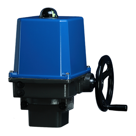
Summary of Contents for PS Automation PSQ-E Series
- Page 1 Operating Instructions PSQ-E Version 2019/01/08 2019 PS Automation GmbH...
-
Page 2: Table Of Contents
Contents Type key ................................2 1. Symbols and safety ............................3 2. Usage as per specification..........................4 3. Storage ................................4 4. Operating conditions ............................. 4 4.1 Installation position ........................... 5 5. Function ................................. 5 6. Manual operation ............................6 7. -
Page 3: Symbols And Safety
1. Symbols and safety Danger signs The following danger signs are used in this operating manual: Caution! There is a general risk of damage related to health and/or properties. Danger! Electrical voltages are present that may lead to death. Life threatening risks may occur due to electrical voltages! Avoid personal or material damages by observing applicable regulations and safety standards! Other notes... -
Page 4: Usage As Per Specification
2. Usage as per specification PSQ-E quarter turn actuators are exclusively designed to be used as electric valve actuators. They are meant to be mounted on valves in order to run their motors. Any other use is considered to be non-compliant and the manufacturer cannot be held liable for any damage resulting from it. -
Page 5: Installation Position
Figure 1: Installation dimensions PSQ-E100 and PSQ-E150 4.1 Installation position Outdoor usage: When using actuators in environments with high temperature fluctuations or high humidity, we suggest a heating resistor to be fitted to prevent the build-up of condensation within the enclosure. Figure 2: Installation position 5. -
Page 6: Manual Operation
6. Manual operation The actuators are supplied with loose enclosed crank. Mount the crank according to figure 3. Figure 3 Crank ssembly The handwheel does provide manual operation in case of power failure or commissioning. It is idle when the motor is operating and always ready for operation without clutching or declutching. Do not exceed the adjusted electrical stroke limits by using the hand wheel The mechanical stop must be set... -
Page 7: Valve Mounting
7. Valve mounting The PSQ-E actuators are provided with a mechanical interface according to ISO 5211 for valve mounting. The gear does contain an internal octagon SW22 to connect the actuator to the valve shaft. Check if the actuator flange suits the valve flange ... -
Page 8: Setting Of The Position Indicator
8.1 Setting of the Position Indicator The position indicator is a two-coloured half ball turning under a transparent dome with blackened quarter segments. Take off the cover and turn the half ball as appropriate to adjust the position indicator. Figure 7: position indicator 9. -
Page 9: Setting Of The Additional Position Switches
Switching cam for ① position switch OPEN/ Feedback signal Switching cam for ② position switch CLOSE/ Feedback signal Switching cam for ③ limit switch OPEN/ Motor cut-off Switching cam for ④ limit switch CLOSE/ Motor cut-off Supporting bridge for screwdriver NOTE: Use the bridge (Figure 8, Pos. -
Page 10: Wiring Diagram
10.1 Wiring diagram Figure 10 shows the standard electrical connections. However, the wiring diagram inside the actuator hood is valid for the specific actuator. For any optional extras see the individual wiring diagram in the related service instructions. Two adjustable limit switches are installed to limit the stroke of the actuator, and cut-off the motor current in the relative direction. -
Page 11: Spare Parts
PSQ actuators are very robust functional units. In case of malfunction or damage of any component, spare parts are available as per a separate spares price list. Please contact PS Automation GmbH or the appropriate representative. Rejected actuators can be returned to our works in Bad Duerkheim, Germany, or to our representatives, for evaluation of failures and repair. -
Page 12: Declaration Of Incorporation Of Part Completed Machinery And Ec Declaration Of Conformity In Compliance With The Directives On Emc And Low Voltage
13.2 Declaration of Incorporation of Part Completed Machinery and EC Declaration of Conformity in compliance with the Directives on EMC and Low Voltage... - Page 13 Apartado de Correos, 142 E-43480 Vila-Seca (Tarragona) India Phone: <+34> 9 77 39 11 09 Fax: <+34> 9 77 39 44 80 PS Automation India Pvt Ltd. E-mail: hans@sertemo.com Srv. No. 25/1, Narhe Industrial Area, A.P. Narhegaon, Tal. Haveli, Dist.


Need help?
Do you have a question about the PSQ-E Series and is the answer not in the manual?
Questions and answers