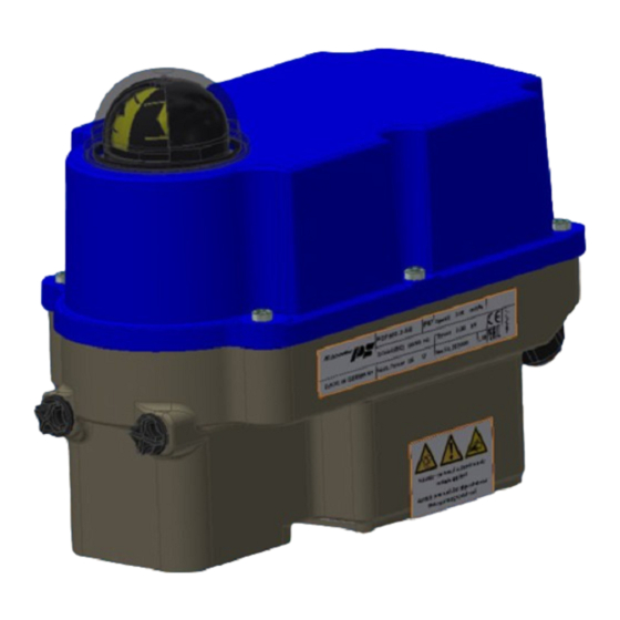
Summary of Contents for PS Automation PSF-Q
- Page 1 Operating Instructions PSF-Q Version 2022/03/24 ©2022 PS Automation GmbH Subject to changes!
-
Page 2: Table Of Contents
14.2 Maintenance ............................... 14 14.3 Spare parts ................................14 15. Decommissioning and disposal ..........................14 11. Appendix ................................... 14 16.1 Accessories ................................14 Type key PSF-Q 50 / CW / 22 W / / 50 Nm / 25 s / Example... -
Page 3: Symbols And Safety
General dangers of non-compliance with safety regulations PSF-Q actuators are built at state-of the art technology and are safe to operate. Despite of this, the actuators may be hazardous if operated by personnel that has not been sufficiently trained or minimum instructed, and if the actuators are handled improperly, or not used as per specification. -
Page 4: Usage As Per Specification
2. Usage as per specification • PSF-Q actuators are exclusively designed to be used as electric valve actuators. They are meant to be mounted on valves in order to run their motors. • Any other use is considered to be non-compliant and the manufacturer cannot be held liable for any damage resulting from it. -
Page 5: Function
Figure 2: Mounting positions 5. Function The PSF-Q electric actuators are designed for the operation of 90° quarter-turn actuators. For mechanical connection to the valve, the actuators are equipped with flanges according to ISO 5211. The torque generated by a brushless DC motor (BLDC) is transmitted via a multi-stage spur gear spur gearbox to a coupling with double square drive. -
Page 6: Valve Mounting
7. Valve mounting The PSF-Q actuators are designed with a mechanical interface according to ISO 5211 for valve mounting. The gear contains an exchangeable drive bush to connect the actuator to the valve shaft. • Check if the actuator flange suits the valve flange. -
Page 7: Adjustment Of The Position Indicator
PSF-Q electric actuators do not have an internal electrical power switch. A switch or power mains switch must be provided in the building installation. It should be positioned closely to the device and be easily accessible for the user and shall be labelled as the mains isolator switch for the actuator. -
Page 8: Wiring Diagram
10.2 Wiring diagram Figure 7 indicates the electrical connections for standard actuators. The wiring diagram inside the actuator is binding for the specific actuator wiring. For any optional accessories, see the separate wiring diagram in the corresponding installation instructions. *optional Figure 7: Electric supply PE earth connection has to be connected to gear casing at... -
Page 9: Signalisation And Functions
11. Signalisation and functions 11.1 DIP switches Function Signal Set value Position feedback Voltage Current Function Control via set value Control via binary inputs Output valve shaft counterclockwise (CCW) with increasing set value Output valve shaft clockwise (CW) with increasing set value Close with torque / Open with torque... -
Page 10: Operating Direction
11.2 Operating direction Actuator CW Spring drives output valve shaft CW DIP switch S2.1 Off Travel end position Torque end position DIP switch S2.1 On Torque end position Travel end position Actuator CCW Spring drives output valve shaft CCW DIP switch S2.1 Off Travel end position Torque end position DIP switch S2.1 On... -
Page 11: Status Display
11.4 Status display Green LED Red LED Actuator not commissioned Is flashing quickly Normal operation / Actuator running Normal operation / Actuator stationary Manual mode active Is flashing alternately Is flashing alternately Manual mode: output valve shaft Is flashing counterclockwise (CCW) Manual mode: output valve shaft Is flashing clockwise (CW) -
Page 12: Manual Operation
12. Operation All internal parameters, like required motor torque, actual position, functional status, etc., are being permanently monitored during operation of the actuator PSF-Q. This ensures that the actuator positions with optimum accuracy, and closes the valve always tightly. Cut-off in end positions Depending on the selected switch position S2-3/4/9, it is determined how the actuator approaches an end position. -
Page 13: Valve Curve
12.2 Valve curve Switch position S2-10 can be used to select the relationship between the set value and the actuator position. Two curves are available. With the linear valve curve, the actuator position in % corresponds to the set value in %. The "Quick Opening Curve"... -
Page 14: Maintenance
14.2 Maintenance The actuators have a pre-tensioned spring inside, the gearbox housing must not be opened. Defective actuators should be returned to our plant in Bad Duerkheim, Germany, or to our representatives, to be checked for damages and their possible causes. 14.3 Spare parts Damaged actuators should be returned to our plant in Bad Duerkheim, Germany, or to our representatives, to be checked for damages and their possible causes. - Page 15 16.2 Declaration of incorporation of part completed machinery and EC declaration of conformity in compliance with the directives on EMC and low voltage...
- Page 16 Our representatives: Italy India PS Automazione S.r.l. PS Automation India Pvt. Ltd. Via Pennella, 94 Srv. No. 25/1, Narhe Industrial Area, I-38057 Pergine Valsugana (TN) A.P. Narhegaon, Tal. Haveli, Dist. IND-411041 Pune Phone: <+39> 04 61-53 43 67 Fax: <+39> 04 61-50 48 62 Phone: <+ 91>...


Need help?
Do you have a question about the PSF-Q and is the answer not in the manual?
Questions and answers