
Related Manuals for PS Automation PS-AMS1x PSL 4


Summary of Contents for PS Automation PS-AMS1x PSL 4
- Page 1 PS-AMS1x PSL Model 4 Operating Instructions PS-AMS1x PSL Model 4 Version 2024/02/06 ©2024 PS Automation GmbH Subject to changes without notice!
-
Page 2: Table Of Contents
Contents Contents ..................................2 1. Symbols and safety ..............................3 2. Usage as per specification ............................4 3. Storage ..................................4 4. Operating conditions ..............................4 4.1 Installation position ............................5 5. Function ..................................5 6. Manual operation ..............................6 7. -
Page 3: Symbols And Safety
1. Symbols and safety General dangers of non-compliance with safety regulations PS-AMS PSL actuators are built at state-of the art technology and are safe to operate. Despite of this, the actuators may be hazardous if operated by personnel that has not been sufficiently trained or at least instructed, and if the actuators are handled improperly, or not used as per specification. -
Page 4: Usage As Per Specification
Other notes The motor surface temperature may rise when maintaining, inspecting and repairing the actuator immediately after the operation. There is a danger of burning the skin! Always consult the relevant operating instructions when mounting PS accessories or operating the actuator with PS accessories. -
Page 5: Installation Position
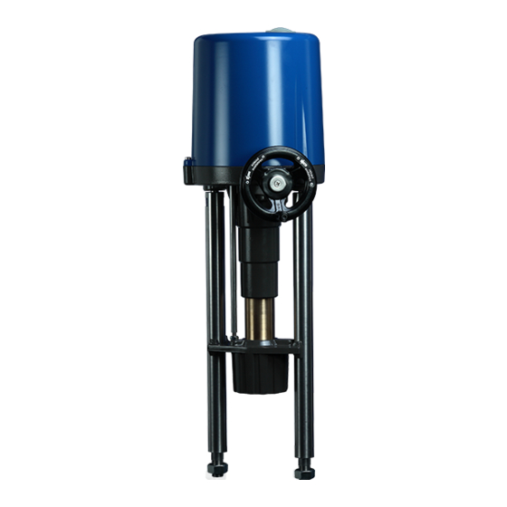
PS-AMS PSL208-214 PS-AMS PSL208-214 PS-AMS PSL320-325 PS-AMS PSL202-204 (Stroke 1.97 in.) (Stroke 2.56 in.) Figure 1: Dimensional data 4.1 Installation position Outdoor usage: When using the actuators in environments with high temperature fluctuations or high humidity, we recommend using a heating resistor as well as a higher enclosure rating (optional accessories). -
Page 6: Manual Operation
6. Manual operation The actuators are supplied with a loosely enclosed handwheel in order to operate the actuator in case of power loss or during installation work such as mounting onto a valve or setting the limit positions. Mount the handwheel according to Figure 3. -
Page 7: Valve Mounting
7. Valve mounting 7.1 PS-AMS PSL202-214 Note: The pictures below show the mounting of a PS-AMS PSL204. The steps are identical for all types. When mounting the actuator onto the valve, use the handwheel and do not drive the actuator electrically. If these instructions are not observed, it may result in personal injury or damage to the actuator and/or valve. - Page 8 ④ ⑤ Pillar end appr. 0.197 in. Mounting Mounting base base Appr. 0.197 in. Move the coupling down until it hits the valve stem. Pillar nut Continue moving until there is a 0.197 in. gap Leave gap between 0.197 in. between the pillar end and the mounting base.
-
Page 9: Ps-Ams Psl320-325
7.2 PS-AMS PSL320-325 When mounting an actuator onto a valve, never drive the actuator electrically but use the handwheel. If these instructions are not observed, it may result in personal injury or damage to the actuator and/or valve. spindle nut grub screw coupling piece counter nut... -
Page 10: Force/Stroke-Dependent Limit Switch Cut-Off
7.3 Force/Stroke-Dependent Limit Switch Cut-Off Figure 6: Standard disc spring coupling The different methods of arranging the discs are dependent on the type of valve. Three different methods are possible: A: Arrangement for a through-valve with "Valve stem retracting" as direction of closing (Figure 6). B: Arrangement for a 3-way valve (Figure 6). -
Page 11: Cover Removal
8. Cover removal Please observe the label on the cover of the actuator. Attention! Observe precautions for handling. Ground the actuator. Before opening the cover, touch grounded housing parts. PS-AMS PSL202 – PS-AMS PSL210 (IP65) Remove the handwheel by loosening it. Pull the cover upwards. -
Page 12: Wiring Diagram
Yellow-and-green coded cords may only be used for connection to protective earth. When leading wires through the conduit entries on the actuator, their minimum bending radius has to be considered. The electric actuators PS-AMS PSL are not fitted with an internal electric isolator, hence a switching device or circuit breaker must be integrated in the facility. -
Page 13: Mains Supply
9.3 Mains supply 9.3.1 Mains supply 1-phase AC/DC Electrical connection work may only be carried out by an authorised professional. Isolate the power supply. Safeguard the line against unauthorized and unintended restarting. Open the terminal box. The terminal box provides terminals to accommodate rigid and flexible cables of wire widths of 0.00022 in.²... -
Page 14: Mains Supply Ps-Ams Psl320/325 With Integrated Local Control Station Psc.2
9.3.2 Mains supply PS-AMS PSL320/325 with integrated local control station PSC.2 Isolate the power supply. Safeguard the line against unauthorized and unintended restarting. Open the cover of the local control station PSC.2. Figure 9: Opening the cover Feed the cable trough the conduit entries in the inner room of the cover. -
Page 15: Interfaces
Figure 12: Wiring diagram with local control PSC.2 or terminal box for 3-phase AC 9.4 Interfaces The actuator PS-AMS PSL has several interfaces inside the terminal box which can be configured by the parameterizing software PSCS or by the local control station PSC.2 (see relevant manuals). 9.4.1 Communication interface For communication and parameterization with a PC or a hand-held device, connect the communication cable to the RJ45-connector. -
Page 16: Sensor Feedback For Process Controller (Optional)
9.4.2.2 Sensor feedback for process controller (optional) Terminals 15 to 17 are used to receive a process sensor‘s feedback to the - optional - process controller, in the parameterisable range 15 16 17 of 0-20 mA or 0-10 V. Caution! The following binary inputs (9.4.2.3 und 9.4.2.4) have priority over the modulating set-value. -
Page 17: Additional Signal Switches (Optional)
9.4.3.2 Additional signal switches (optional) The activation points of the optionally available signal switches are freely adjustable via cams. Terminals 18/19 and 20/21 provide 18 19 20 21 potential-free opening or closing contacts. The standard switches are rated to 230 VAC/10 A (6 A inductively). Special switches with gold plated contacts are available for low power (up to 100 mA and 30 V). -
Page 18: Adjusting Additional Signal Switches (Optional)
In actuators PS-AMS PSL the heating resistor is powered via the power supply of the actuator, so it does not have to be fed separately. For retro-fitting the heating resistor, wiring of the two cables has to be made to the terminals on the main board as per the figure on the left. -
Page 19: Status Display / Calibration Elements
10. Status display / Calibration elements A red and a green LED on top of each other inside the terminal box indicate the status of the actuator. Another single red LED (optional) signals the status of the optional fieldbus interface. -> See special operating manual for PS-AMS fieldbus. -
Page 20: Cut-Off In End Positions
12.1 Cut-off in end positions Cut-offs of the PS-AMS PSL actuators can be adjusted to meet the valve function in an optimum way by using the communication software PSCS (using a special interface cable, or optionally bluetooth connection). This will result in different behavior of the actuator. In case a position is surpassed or not reached, this can be read out via the fault indication relay or via the communication software PSCS. -
Page 21: Auto-Calibration
13.1 Auto-calibration of the cut- (Only available if at least one offs is set to be “by force/torque” or “by position automatically”.) ② ① Press the commissioning button for 3 sec Calibration in progress (Green LED is flashing, (For position of commissioning button please actuator drives in both positions). -
Page 22: Status Messages
14. Status messages 14.1 Fault indicator relay Fault messages can be transmitted to the control room with a maximum load of 24 VDC/100 mA via a closing contact at terminals 7 and 8. The messages can be parameterized via software PSCS. The contact between terminals 7 and 8 is closed when there is no fault and the drive is supplied with power. -
Page 23: Accessories
18. Accessories Various options are available in order to adapt the actuators to the various service conditions. A list of accessories for each actuator type is shown on the actuator data sheet. Potential-free additional signal switches with silver contacts Add. Signal Switches (0.1 A - 5 A switching current) Potential-free additional signal switches with gold contacts Add. -
Page 24: Tracing Faults Chart
19. Tracing faults chart Red LED Green LED Status Probable reasons Possible remedy Actuator does not respond, both 1) No supply voltage applied 1) Check mains supply LEDs are off 2) The applied voltage does 2) Apply correct supply not match the actuator voltage voltage on the tag plate Actuator does not drive the full... - Page 25 Red LED Green LED Faults within the actuator’s Probable reasons Possible remedy environment Actuator drives into a preset 1) Signal is applied to the 1) Disconnect the signal position binary fail-safe input 2) Check supply voltage 2) Supply voltage failure on actuators with optional PSCP Set-value disconnected or outside...
-
Page 26: Ec Declaration Of Conformity
20. EC declaration of conformity... - Page 27 Our representatives: Italy India PS Automazione S.r.l. PS Automation India Pvt. Ltd. Via Pennella, 94 Srv. No. 25/1, Narhe Industrial Area, I-38057 Pergine Valsugana (TN) A.P. Narhegaon, Tal. Haveli, Dist. Phone: <+39> 04 61-53 43 67 IND-411041 Pune Fax: <+39> 04 61-50 48 62 Phone: <+ 91>...
Need help?
Do you have a question about the PS-AMS1x PSL 4 and is the answer not in the manual?
Questions and answers