
Related Manuals for PS Automation PSF-M-EX Series


Summary of Contents for PS Automation PSF-M-EX Series
- Page 1 PSF-M-EX IECEx TPS 22.0019X Operating Instructions Version 02/10/2023 Art. No.: 8035626 ©2023 PS Automation GmbH Subject to changes...
-
Page 2: Table Of Contents
Content 1. Product description ............................... 3 2. Applicable standards ..............................3 3. Key figures ..................................4 3.1 Type code ................................5 4. Symbols used and safety ............................... 5 5. Intended use ................................. 6 5.1 Special conditions ..............................7 6. Storage ..................................7 7. -
Page 3: Product Description
Conduit entries are available in the lower section of the housing for inserting the electrical cables. The construction, as well as the interaction of the individual components and the housing regarding their suitability for use in hazardous areas, are tested by PS Automation GmbH and confirmed by the identification with the type label. -
Page 4: Key Figures
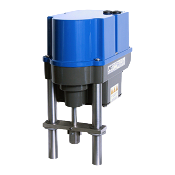
3. Key figures Certificate No. IECEx TPS 22.0019X Ex marking Ex db eb IIC T6 Gb Ex db eb IIC T4 Gb or rather Ex tb IIIC T80 °C Db Ex tb IIIC T100 °C Db Size (electrical section) approx. 240 x 135 x 181 mm (WxLxH) (Ex e/Ex t housing) Actuating power Depending on variant... -
Page 5: Type Code
3.1 Type code Example PSF-M-402-EX 24VAC / 50-60Hz / 5,0kN Actuator type Voltage supply Frequency Max. input power Force Stroking speed [mm/s] 4. Symbols used and safety General dangers in case of non-observance of the safety instructions The PSF-M-Ex actuators are built according to the latest state of the art and are operationally safe. Nevertheless, hazards can arise from the actuators if they are not used by trained or at least instructed personnel and/or are used improperly or for purposes other than those for which they are intended. -
Page 6: Intended Use
Notice of hazards The following hazard symbols are used in these instructions: Attention! There are general hazards that can lead to property and/or personal injury. Caution! Life threatening electrical voltages may be present! Danger! This symbol warns of an imminent danger to the health of persons. Failure to follow these notices may result in injury. -
Page 7: Special Conditions
Assembly/disassembly, operating and maintenance work may only be carried out by suitable skilled personnel familiar with the work. All generally applicable legal regulations and other binding guidelines for work safety, accident prevention and environmental protection must be complied with. ... - Page 8 Installation The conductor must be connected carefully at the terminal points so that the individual wires are not damaged. The maximum connection data on the type plate and the applicable documents must be taken into consideration. The device must be integrated into a suitable earthing or equipotential bonding system before commissioning, a connection part (4 mm²) is available for this purpose on the underside of the actuator.
-
Page 9: Manual Override And Setting Of The Dip Switches
8. Manual override and setting of the DIP switches 8.1 Setting the actuators during commissioning (hood open) When commissioning the actuators, the hood must be opened. The hood may only be opened in non-hazardous areas and only in a dry environment (see chapter 10 for instructions). To actuate the actuator during setting work (valve assembly and end position setting), an electrical manual override by means of a push button is available (for operation, see chapter 12.2). -
Page 10: Setting The Actuators During Operation (Hood Closed)
8.2 Setting the actuators during operation (hood closed) To actuate the actuator during setting work in potentially explosive atmospheres (end position setting), an electrical manual override by means of a push button is provided in the hood (for conditions see chapter 12.2). To reach the manual override, the screw plugs must be opened. -
Page 11: Valve Mounting
9. Valve mounting Spring-loaded clamp with coupling pin Pillar Coupling Locking nut Valve stem 1 mm Bracket Pillar nut Figure 5: Valve mounting 9.1 Valve mounting for cut-off by force at extended actuator stem Initial position: Valve stem is retracted, actuator stem is extended 1. -
Page 12: Opening And Closing The Hood
10. Opening and closing the hood The hood may only be opened in non-hazardous areas and only in a dry environment. Take appropriate ESD handling precautions before opening the housing: Earth the actuator. Touch earthed housing parts before opening the hood. Opening: Hexagon socket screw... -
Page 13: Electric Supply
11. Electric supply 11.1 Safety instructions During the connection of the mains voltage, this must be disconnected and secured against unintended reactivation. The actuator hood must be opened for the electrical connection (see chapter 10). The mains connection cables must be designed for the nominal current of the actuator. Yellow-green coloured wiring shall be used only for connecting the protective earth connections. -
Page 14: Connection Diagram
11.2 Connection diagram Figure 7 shows the electrical connection for standard drives. The wiring diagram in the actuator is binding for the connection. For the connection of optional accessories, please refer to the respective operating instructions. Figure 7: Electrical connection Figure 8: Connection for potential equalisation PE earth connection has to be connected to gear casing at The connection for equipotential bonding is made at the external equipotential bonding connection... -
Page 15: Display And Functions
12. Display and functions 12.1 DIP switches Function Signal Set value Position feedback Voltage Current function Control via set value Control via binary inputs Extend valve stem with increasing set value Retract valve stem with increasing set value Closing with force / opening with force Closing with force / opening with stroke Closing with force / opening with 20 mm stroke... -
Page 16: Operating Buttons
12.2 Operating buttons Function Action Button B1 Button B2 LED sequence Both LEDs flash Activate Press for > 3 sec. Press for > 3 sec. alternately Retract valve stem Press Green LED flashes Manual Extend valve stem Press Red LED flashes operation Both LEDs flash Stop... -
Page 17: Status Display
12.3 Status display Green LED Red LED Actuator not calibrated Flashes rapidly Normal operation / actuator moves Normal operation / actuator stationary Manual mode active Flashes alternately Flashes alternately Manual mode: Valve stem is Flashes extended Manual mode: Valve stem is Flashes retracted Automatic commissioning running... -
Page 18: Manual Operation (See Also Chapter 12.2)
The calibration of the two end positions is started and saved by pressing B1 and B2 simultaneously for at least 3 seconds. After successful calibration, the green LED flashes seven times. Then press button B1 to return to normal operation. ... -
Page 19: Operation
13. Operation The operator of an electrical system in a potentially explosive environment must keep the equipment in proper condition, operate it properly, monitor it and carry out maintenance and repair work. See also IEC 60079-17/IEC 60079-19. During operation, all internal parameters, such as the required motor torque and the current position, as well as the operating states of the actuator are continuously monitored. -
Page 20: Valve Curve
13.2 Valve curve Switch position S2-10 can be used to select the relationship between the set value and the actuator position. Two curves are available. With the linear valve curve, the actuator position in % corresponds to the set value in %. The "Quick Opening Curve"... -
Page 21: Maintenance And Servicing
15. Maintenance and servicing The actuators are maintenance-free under the operating conditions specified in the data sheet. The gearboxes are lubricated for life and do not require relubrication. Attention! During maintenance and servicing, the actuator must not be operated electrically. Personnel carrying out work and maintenance and servicing must be skilled and familiar with the work. -
Page 22: Decommissioning And Disposal
16. Decommissioning and disposal Disconnect the mains connection and secure it against accidental reactivation. Open the hood. Remove external connections. Remove the actuator from the valve. Disposal The actuator is considered waste from electrical and electronic equipment and shall not be disposed of as household waste. - Page 23 Our representatives: Italy India PS Automazione S.r.l. PS Automation India Pvt. Ltd. Via Pennella, 94 Srv. No. 25/1, Narhe Industrial Area, I-38057 Pergine Valsugana (TN) A.P. Narhegaon, Tal. Haveli, Dist. Tel.: <+39> 04 61-53 43 67 IND-411041 Pune Fax: <+39> 04 61-50 48 62 Tel.: <+ 91>...
Need help?
Do you have a question about the PSF-M-EX Series and is the answer not in the manual?
Questions and answers