
Related Manuals for PS Automation PS-AMS PSQ Series


Summary of Contents for PS Automation PS-AMS PSQ Series
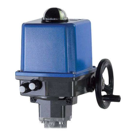
- Page 1 Operating Instructions PS-AMS Series PSQ Subject to changes! Version 2018/11/19 ©2018 PS Automation GmbH...
-
Page 2: Table Of Contents
Table of Contents 1. Symbols and safety ..............................3 2. Usage as per specification ............................4 3. Storage ..................................4 4. Operating Conditions and Installation Position ......................4 4.1 Operating Conditions .............................. 4 4.2 Installation Position ..............................5 5. Operating Principle ..............................6 6. -
Page 3: Symbols And Safety
1. Symbols and safety General dangers of non-compliance with safety regulations PSQ-AMS actuators are built at state-of the art technology and are safe to operate. Despite of this, the actuators may be hazardous if operated by personnel that has not been sufficiently trained or at least instructed, and if the actuators are handled improperly, or not used as per specification. -
Page 4: Usage As Per Specification
Always consult the relevant operating instructions when mounting PS accessories or operating the actuator with PS accessories. Connections for signal in- and output are double isolated from circuits that can be under dangerous voltage. 2. Usage as per specification ... -
Page 5: Installation Position
Figure 1: Outside dimensions Actuator type PSQ 103 AMS PSQ 203 AMS PSQ 503/703 AMS PSQ 1003 AMS 4.2 Installation Position The actuator may be mounted in any desired position except “cover facing downwards”. Figure 2: Installation position Outdoor usage: When using the actuators in environments with high temperature fluctuations or high humidity, we recommend using a heating resistor as well as a higher enclosure rating (optional accessories). -
Page 6: Operating Principle
5. Operating Principle The quarter-turn actuators PSQ-AMS are designed for the use as electric valve actuators. Mounting to the valve is done by a mounting flange as per ISO5211, plus an exchangeable drive bushing with an inside contour as per the valve shaft. -
Page 7: Mechanical Mounting
7. Mechanical Mounting 7.1 Safety Note Beware of mechanical hazards due to electrically powered actuator components! With the actuator powered electrically, operating the unit holds the danger of crushing your fingers, damaging the actuator and/or the valve. During adjustment work, the actuator may be operated by means of the hand wheel only. -
Page 8: Electrical Connection
8. Electrical Connection 8.1 Safety Note When performing electric work on this unit, the local accident prevention regulations must be followed. Observe EN 60204-1 (VDE 0113 part 1) to ensure human safety, integrity of the assets as well as the proper functioning of the unit. Electric supply lines must be dimensioned for the peak current of the unit and comply with IEC 227 and IEC 245. - Page 9 Wiring to the main board: Wiring to the terminal box: Figure 7: Open the cover Figure 9: Open the terminal box Open the cover. Insert the cable into the actuator Open the cover of the terminal box. Insert the via the cable glands. cable through the cable glands to the inside of the cover.
- Page 10 Figure 11: Wiring diagram for wiring to the main board Figure 12: Electrical terminals with local control PSC.2 with 1-phase AC/DC The wiring diagram with Fieldbus and the above mentioned wiring diagrams are supplied with the actuator.
- Page 11 Figure 13: Electric terminals with local control PSC.2 with 3-phase AC Caution: Please observe the supply voltage and the maximum power consumption of the actuator as indicated on Figure 12: Wiring diagram for wiring to the terminal box the actuator‘s name plate! Close the cover of the actuator: Close the cover of the terminal box: Wiring of Protective Earth (PE) has to be...
-
Page 12: Input Terminals
8.3.2 Input Terminals 8.3.2.1 Set-Value Terminals 1 through 3 are used to receive a parameterisable modulating set-value for control operation within the range of 0-20 mA or 0-10V. 8.3.2.2 Sensor Feedback for Process Controller (optional) Terminals 15 through 17 (main board) resp. 10 through 12 (terminal box) are used to receive a process sensor‘s feedback to the - optional - process controller, in the parameterisable range of 0-20 mA or 0-10 V. -
Page 13: Fieldbus Interface (Optional)
Main board: terminals 7 + 8 Terminal box: terminals 20 + 21 8.3.4 Fieldbus interface (optional) Optionally a fieldbus interface can be fitted to the AMS-actuator, with wiring to a terminal block or an external socket. -> See special operating instruction for AMS-Fieldbus. 8.4 Accessories 8.4.1 Space Heater (optional) Actuators PSQ-AMS can be fitted with a space heater. -
Page 14: Status Display / Operating Element / Communication
The cams for activating the switches are mounted on a shaft by means of a friction coupling. They are adjustable by a screwdriver with a small end, using the bride (3) as support. At actuators closing clockwise, the lower cam (1) activates the switch for closing direction, the upper cam (2) for opening direction. -
Page 15: Operation
10. Operation All internal parameters, like required motor torque, actual position, functional status, etc., are being permanently monitored during operation of the actuator PS-AMS. This ensures that the actuator positions with optimum accuracy, and closes the valve always tight. Deviations can be read out via communication software PSCS or via local control PSC.2 (see respective instruction manuals), or can be displayed to the control room using the optional fault indication relay. -
Page 16: Adjusting The Mechanical Stop
During automatic commissioning the actuator goes through the full programmed valve stroke / angle automatically. Parameters specific to the valve are being measured and calculated values are permanently stored in the actuator. At the same, set value and position feedback range are scaled. To enable Automatic Commissioning, a mechanical stop is required in at least one end position (usually the closed position) of the valve. -
Page 17: Unscrewing The Mechanical Stop
The automatic commissioning run start now. The actuator will drive through the full adjusted range. The green LED flashes quickly during this commissioning run. After finishing it the actuator is ready for operation. The green LED glows permanently as long as there is no malfunction. -
Page 18: Manual Commissioning
Note Automatic commissioning can be started via software PSCS -> See relevant operation manuals Caution! If the LEDs display other types of signals than “flashing green” or “glowing green permanently”, please refer to the chapter 15 on “Tracing Faults”. Caution! The mains supply must not be interrupted during the commissioning run! 11.2 Manual Commissioning... -
Page 19: Maintenance And Repair
12. Maintenance and Repair Maintenance Under the conditions of use as per specification as lined out in the data sheet, the PS-AMS actuators are free of maintenance. All gears are lubricated for their service life and do not require to be re-lubricated. Cleaning Clean the actuators with a dry soft cloth and do not use any cleaning agent. -
Page 20: Tracing Faults
15. Tracing faults Red LED Green LED Status Probable reasons Possible remedy x Actuator does not 1) No supply voltage applied 1) Check mains supply respond, both LEDs are 2) The applied voltage does not 2) Apply correct supply voltage match the actuator voltage on the tag plate Actuator does not drive... - Page 21 Red LED Green LED Faults within the Probable reasons Possible remedy actuator’s environment 3) No process sensor signal available Actuator drives into a 1) Signal is applied to the 1) Disconnect the signal preset position binary fail-safe input 2) Check supply voltage 2) Supply voltage failure on actuators with optional PSCP x Set-value disconnected...
-
Page 22: Ce Declaration Of Conformity
16. CE Declaration of Conformity... - Page 24 Apartado de Correos, 142 E-43480 Vila-Seca (Tarragona) India Tel. : <+34> 9 77 39 11 09 PS Automation India Pvt. Ltd. Fax : <+34> 9 77 39 44 80 Srv. No. 25/1, Narhe Industrial Area, E-mail : hans@sertemo.com A.P. Narhegaon, Tal. Haveli, Dist.
Need help?
Do you have a question about the PS-AMS PSQ Series and is the answer not in the manual?
Questions and answers