
Related Manuals for Parker Sporlan Subcool Control


Summary of Contents for Parker Sporlan Subcool Control
- Page 1 July 2020 / Bulletin 100-50-5.2 Bulletin 100-50-5.2 – Page 1 Subcool Control Installation and Operation Instructions Controller v. G.1...
-
Page 2: Table Of Contents
The user must analyze all aspects of the application, follow applicable industry standards, and follow the information concerning the product in the current product catalog and in any other materials provided from Parker or its subsidiaries or authorized distributors. -
Page 3: Installation
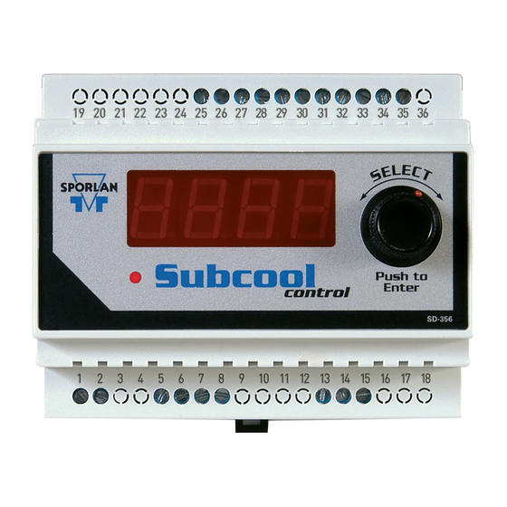
It displays actual leaving liquid temperature, superheat, NOTE: The Sporlan Subcool Control should be installed suction pressure, valve position, controller status, only by a qualified professional. All other system com- and alarms. -
Page 4: Setup
Once powered up, the controller will display the firmware versions for the display and the controller. It will then display The Sporlan Subcool Control uses an interactive control the first variable to set. scheme for Subcooling and Superheat operation. The con- troller optimizes the use of the heat exchanger based on the , Step Motor Stroke. -
Page 5: Controller Networking
The Subcool Control will allow a full and partial block read of the Input The Sporlan Subcool Control offers the ability to control and Holding registers and coils. the subcooler expansion valve manually. This feature can be... -
Page 6: Pid Tuning
RS485 network requirements. 6. PID Tuning The Sporlan Subcool Control is factory programmed with de- fault Proportional–Integral–Derivative (PID) settings that will Controller 1 provide efficient control. It may be necessary, however, to fine tune the PID settings in applications where systems experi- ence rapid transient conditions (such as frequent “impulse”... -
Page 7: Troubleshooting
Bulletin 100-50-5.2 – Page 7 Pressure transducers should be tested while connected to These actions are inversely proportional in nature. If the sub- the controller and powered. Test at the controller terminals. cooled liquid temperature or Superheat are slow to react to a Voltage between terminals 34 and 35 should be 4.8 - 5.2 volts transient system change, then the Proportional may be too low DC. - Page 8 Page 8 – Bulletin 100-50-5.2 Table 4 - Troubleshooting SYMPTOM CHECK Wiring terminals (power) at transformer and controller Will not power up Supply voltage (see Technical Specification section) EPR valve setting (too low) Subcooling below setpoint Pressure Transducer Range (correct transducer set up in controller; 0-300, etc.) Pressure Transducer Type (correct transducer set up in controller;...
-
Page 9: Appendix A Setup Menu
Bulletin 100-50-5.2 – Page 9 APPENDIX A - Setup Menu SETUP MENU Display Readout Description 1596 Step Bipolar Valve 16 Valve Type 313 3193 Step Bipolar Valve StEp Default is 2500 00 00 2500 Step Bipolar Valve 636 6386 Step Bipolar Valve 400 Step Unipolar Valve Display Readout Description r... -
Page 10: Appendix B Process Values
Page 10 – Bulletin 100-50-5.2 APPENDIX B - Process Values PROCESS DESCRIPTION CADR Controller display address must be reset* LovT Liquid Outlet Temperature SvPH Superheat (tout-tsat) SvcP Suction Pressure Conversion of suction pressure to its tSAt saturated temperature tovt Sensible heat out of the evaporator PoSn Position of the EEV step motor Liquid Inlet Temperature (Optional) -
Page 11: Appendix E Setpoint Parameters
Bulletin 100-50-5.2 – Page 11 APPENDIX E - Setpoint Parameters PARAMETERS Escape and Save Settings — Liquid Outlet Temperature Setpoint 10 to 100°F (-12.3 to 37.7°C) LoSP Change to desired Liquid Out Temperature Default is 75°F (23.8°C) 40 to 120°F (4.4 to 48.8°C) Return Gas High Limit rghL Default is 120°F (48.8°C) - Page 12 Page 12 – Bulletin 100-50-5.2 APPENDIX E - Setpoint Parameters (continued) PARAMETERS 1 to 255 Default is 10 Increase value to decrease valve response Low Superheat Integral Coefficient LSHi to superheat over time, low Superheat condition Cycle Time 1 to 10 seconds C4ct Default is 1 Readout...
-
Page 13: Appendix F Parameter Definitions
Bulletin 100-50-5.2 – Page 13 APPENDIX F - Parameter Definitions DISPLAY MEANING DESCRIPTION Escape from the Settings Menu and Return to Process Escape Variables Menu The target control temperature of the liquid leaving the LoSP Liquid Outlet Temperature Control Setpoint heat exchanger Limits the temperature of the superheated refrigerant to a rghL... -
Page 14: Appendix G Alarms And Failsafes
Page 14 – Bulletin 100-50-5.2 APPENDIX G - Alarms and Failsafes READOUT DESCRIPTION CAUSE and FAILSAFE nonE No Active Alarms Normal Operation When the pressure is outside the operating range. Will force a Pressure Sensor Alarm PSAL pump-down. When the suction temperature is outside the operating range. Suction Temperature Sensor Alarm tSAL (under -60 degrees, over 150 degrees) Will force a pump-down. -
Page 15: Appendix I Wiring Diagram
Bulletin 100-50-5.2 – Page 15 APPENDIX I - Wiring Diagram Black White Dry Contacts (T4) Green Liquid Inlet Temp. (T3) Liquid Outlet Temp. (T2) Evap. Outlet Temp. (T1) Ground White: Signal Green: Ground Black: 5VDC White: "Signal" Green: "Ground" Black: "5VDC"... -
Page 16: Appendix J Sensor Installation
Page 16 – Bulletin 100-50-5.2 APPENDIX J - Sensor Installation Figure 6 - Temperature Sensor Positioning Refer to Appendix I - Wiring Diagram for sensor locations. Mount the Pressure Transducer Position the suction return gas pressure access port near the outlet of the heat exchanger. Verify that the pressure range matches the expected sys- tem operating pressure (i.e 0-150 psig, 0-300 psig, etc). -
Page 17: Appendix Kmodbus Memory Map
Bulletin 100-50-5.2 – Page 17 APPENDIX K - MODBUS Memory Map REGISTER ADDRESS/DESCRIPTION RANGE Read Coils (0x01) 0. Manual Valve Enabled Flag 0 = Disabled 1 = Enabled 1. Manual Valve Duration Enabled Flag 0 = Disabled 1 = Enabled Read Holding Register 0. - Page 18 Page 18 – Bulletin 100-50-5.2 APPENDIX K - MODBUS Memory Map (continued) REGISTER ADDRESS/DESCRIPTION RANGE Read Holding Register 20. Pressure Calibration Offset -5 to 5 PSI (-0.34 to 0.34 Bar) (0x03) 21. Suction Temperature Calibration Offset -5 to 5°F (-2.8 to 2.8°C) 22.
-
Page 19: Temperature Sensor Specifications
Bulletin 100-50-5.2 – Page 19 APPENDIX L - 2K Temperature Sensor Chart °C °F RANGE VDC °C °F RANGE VDC °C °F RANGE VDC °C °F RANGE VDC -51.1 -60 4.375 - 4.555 -18.3 3.017 - 3.142 14.4 1.446 - 1.507 47.2 0.594 - 0.619 -50.6 -59... -
Page 20: Temperature Sensor Specifications
Page 20 – Bulletin 100-50-5.2 APPENDIX M - 3K Temperature Sensor Specifications °C °F RANGE VDC °C °F RANGE VDC °C °F RANGE VDC °C °F RANGE VDC -51.1 -60 4.747 - 4.941 -18.3 3.875 - 4.035 14.4 2.005 - 2.089 47.2 0.719 - 0.750 -50.6 -59... -
Page 21: Temperature Sensor Specifications
Bulletin 100-50-5.2 – Page 21 APPENDIX N - 10K Temperature Sensor Specifications °C °F RANGE VDC °C °F RANGE VDC °C °F RANGE VDC °C °F RANGE VDC -51.1 4.949 - 4.956 -17.2 4.590 - 4.631 16.7 3.327 - 3.427 50.6 1.635 - 1.722 -50.6... -
Page 22: Temperature Sensor Specifications
Standalone Controller with Display Kelvin lld 952568 Remote display unit Power Supply 953444 Kelvin Power Supply 100-240 VAC/24VDC Parker Sporlan Temperature Probes 2k Sensor 952662 Used with or without well 3k Surface Sensor (black) 230545 20 ft. Surface only 3k Air Sensor (black) 230546 20 ft. -
Page 23: Appendix P System Flow Chart
Bulletin 100-50-5.2 – Page 23 APPENDIX P - System Flow Chart Start Control PROCESS Liquid Out & Superheat elapsed? Is return gas T greater than ? Limit Superheat DOCUMENT REVISION HISTORY Revision Date Code Description of Revision Author Approved... - Page 24 © 2020 Parker Hannifin Corporation. Bulletin 100-50-5.2 / 72020 Parker Hannifin Corporation Sporlan Division 206 Lange Drive • Washington, MO 63090 USA phone 636 239 1111 • fax 636 239 9130 www.sporlan.com...
Need help?
Do you have a question about the Sporlan Subcool Control and is the answer not in the manual?
Questions and answers