HIKVISION DS-KD8003-IME1 Quick Start Manual
Video intercom module door station
Hide thumbs
Also See for DS-KD8003-IME1:
- User manual (91 pages) ,
- Manual (6 pages) ,
- Quick start manual (5 pages)

Related Manuals for HIKVISION DS-KD8003-IME1


Summary of Contents for HIKVISION DS-KD8003-IME1
- Page 1 Video Intercom Module Door Station Quick Start Guide Scan to get detailed User Manual...
- Page 2 Trademarks and other Hikvision marks are the property of Hikvision and are registered trademarks or the subject of applications for the same by Hikvision and/or its affiliates. Other trademarks mentioned in this manual are the properties of their respective owners. No right of license is given to use such trademarks without express permission.
- Page 3 Video Intercom Module Door Station·Quick Start Guide TO THE MAXIMUM EXTENT PERMITTED BY APPLICABLE LAW, IN NO EVENT WILL HIKVISION, ITS DIRECTORS, OFFICERS, EMPLOYEES, OR AGENTS BE LIABLE TO YOU FOR ANY SPECIAL, CONSEQUENTIAL, INCIDENTAL, OR INDIRECT DAMAGES, INCLUDING, AMONG OTHERS, DAMAGES...
- Page 4 Video Intercom Module Door Station·Quick Start Guide Regulatory Information FCC Information Please take attention that changes or modification not expressly approved by the party responsible for compliance could void the user’s authority to operate the equipment. FCC compliance: This equipment has been tested and found to comply with the limits for a Class B digital device, pursuant to part 15 of the FCC Rules.
- Page 5 Video Intercom Module Door Station·Quick Start Guide 2006/66/EC (battery directive): This product contains a battery that cannot be disposed of as unsorted municipal waste in the European Union. See the product documentation for specific battery information. The battery is marked with this symbol, which may include lettering to indicate cadmium (Cd), lead (Pb), or mercury (Hg).
- Page 6 Video Intercom Module Door Station·Quick Start Guide Safety Instruction These instructions are intended to ensure that user can use the product correctly to avoid danger or property loss. The precaution measure is divided into Warnings and Cautions: Warnings: Neglecting any of the warnings may cause serious injury or death. Cautions: Neglecting any of the cautions may cause injury or equipment damage.
- Page 7 Video Intercom Module Door Station·Quick Start Guide Cautions Do not drop the device or subject it to physical shock, and do not expose it to high electromagnetism radiation. Avoid the equipment installation on vibrations surface or places subject to shock (ignorance can cause equipment damage). ...
-
Page 8: Table Of Contents
Video Intercom Module Door Station·Quick Start Guide Table of Contents 1 Appearance ....................1 1.1 Main Unit ......................... 1 1.2 Nametag Module ..................... 2 1.3 Keypad Module ......................3 1.4 Indicator Module ..................... 3 1.5 Card Reader Module ....................4 1.6 Blank Module...................... -
Page 9: Appearance
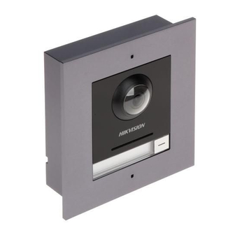
Video Intercom Module Door Station·Quick Start Guide 1 Appearance 1.1 Main Unit Figure 1-1 Main Unit Appearance Table 1-1 Appearance Description Description Microphone Low Illumination IR Supplement Light Built-in Camera Loudspeaker Call Button Nametag TAMPER Network Interface Module-connecting Interface(output) Terminals Nametag area supports insert customized name card. -
Page 10: Nametag Module
Video Intercom Module Door Station·Quick Start Guide 1.2 Nametag Module Figure 1-2 Nametag Module Appearance Table 1-2 Appearance Description Description Call Button Nametag Module-connecting Interface(output) Module-connecting Interface(input) Debug Port Nametag area supports insert customized name card. The suggested card size is: 58 (L) x 11.7(W) mm. -
Page 11: Keypad Module
Video Intercom Module Door Station·Quick Start Guide 1.3 Keypad Module Figure 1-3 Keypad Module Appearance Table 1-3 Appearance Description Description Button Module-connecting Interface(output) Module-connecting Interface(input) Debug Port 1.4 Indicator Module Figure 1-4 Keypad Module Appearance... -
Page 12: Card Reader Module
Video Intercom Module Door Station·Quick Start Guide Table 1-4 Appearance Description Description Indicator1(Solid yellow during calling) Indicator2(Solid white during two-way audio) Indicator3(Solid blue when door is open) Module-connecting Interface(output) Module-connecting Interface(input) Debug Port 1.5 Card Reader Module Figure 1-5 Card Reader Module Appearance Table 1-5 Appearance Description Description Card Reading Area... -
Page 13: Blank Module
Video Intercom Module Door Station·Quick Start Guide 1.6 Blank Module Figure 1-6 Blank Module Appearance Table 1-6 Appearance Description Description Supports to insert customized information card... -
Page 14: Terminal And Wiring
Video Intercom Module Door Station·Quick Start Guide 2 Terminal and Wiring 2.1 Terminal Description 2.1.1 Main Unit Figure 2-1 Terminals and Interfaces Table 2-1 Descriptions of Terminals and Interfaces Interface Description Door Lock Relay Output (NC) Door Lock Relay Output (NO) Common Interface Door Lock Relay Output (NC) Door Lock Relay Output (NO) -
Page 15: Sub Module
Video Intercom Module Door Station·Quick Start Guide Interface Description 485- 485+ Module-connecting Interface 12V OUT PoE Network Interface(Supports IEEE 802.3af/at-Compliant Devices) 2.1.2 Sub Module All the modules except the main work as the sub module. The sub module’s interfaces and terminals as below: Figure 2-2 Terminals and Interfaces Table 2-2 Descriptions of Terminals and Interfaces Interface... -
Page 16: Wiring Description
Video Intercom Module Door Station·Quick Start Guide 2.2 Wiring Description 2.2.3 Door Lock Wiring Figure 2-3 Door Lock Wiring Terminal NC1/COM is set as default for accessing magnetic lock/electric bolt; terminal NO2/COM is set as default for accessing electric strike. ... -
Page 17: Door Magnetic Wiring
Video Intercom Module Door Station·Quick Start Guide 2.2.4 Door Magnetic Wiring Figure 2-4 Door Magnetic Wiring AIN1 and AIN2 are defaulted to connect door magnetic. Door magnetic connected to AIN1 detects status of the lock that connected to NC1/NO1; Door magnetic connected to AIN2 detects the status of the lock connected to NC2/NO2. - Page 18 Video Intercom Module Door Station·Quick Start Guide AIN3 and AIN4 are set as default for connecting exit button. Exit button connected to AIN3 opens the lock connected to NC1/NO1; Exit button connected to AIN4 controls the lock that connected to NC2/NO2.
-
Page 19: Installation
Video Intercom Module Door Station·Quick Start Guide 3 Installation Before you start: Make sure the device in the package is in good condition and all the assembly parts are included. Set the sub module address before start the installation steps. ... -
Page 20: One-Module Installation
Video Intercom Module Door Station·Quick Start Guide 2. Set the sub module address according to the DIP rules, and install the rubber cover back. Digit 1, 2, 3, 4 are used to coding the sub module address; Digit 5, 6, 7, 8 are reserved. ... -
Page 21: One-Module Surface Mounting
Video Intercom Module Door Station·Quick Start Guide The dimension of one module mounting frame is: 117(L)×107(W)×32.7(D) mm. The dimensions above are for reference only. The actual size can be slightly different from the theoretical dimension. 3.2.2 One-Module Surface Mounting Steps: 1. - Page 22 Video Intercom Module Door Station·Quick Start Guide Figure 3-4 Fix the Mounting Frame The mounting frame should be placed exactly as below for this step. The tamper plate should be at the low-right. 5. Connect the cables to the corresponding interfaces of the main unit and insert it into the frame.
-
Page 23: One-Module Flush Mounting
Video Intercom Module Door Station·Quick Start Guide Figure 3-5 Insert the Main unit 6. Use the hexagon wrench in the package fix the cover onto the frame. Figure 3-6 Fix the Cover 3.2.3 One-Module Flush Mounting Steps:... - Page 24 Video Intercom Module Door Station·Quick Start Guide 1. Paste the installation Sticker A onto the wall. Make sure the sticker is placed leveled via measuring with the gradienter. 2. Cave the installation hole along the solid line on Sticker A. The suggested dimension of installation hole is 121(L)×111(W)×33(D) mm.
- Page 25 Video Intercom Module Door Station·Quick Start Guide Figure 3-9 Install Mounting Frame The mounting frame should be placed exactly as below for this step. The tamper plate should be at the low-right. 7. Fill and level up the gap between the frame and wall with concrete. Remove the locating plates after concrete is dry.
- Page 26 Video Intercom Module Door Station·Quick Start Guide Figure 3-10 Insert the Main unit 9. Use the hexagon wrench in the package fix the cover onto the frame. Figure 3-11 Fix the Cover...
-
Page 27: Two-Module Installation
Video Intercom Module Door Station·Quick Start Guide 3.3 Two-Module Installation 3.3.1 Installation Accessory Description Figure 3-12 Front and Side View The dimension of two-module mounting frame is: 219(L)×107 (W)×32.7(D) mm. The dimensions above are for reference only. The actual size can be slightly different from the theoretical dimension. - Page 28 Video Intercom Module Door Station·Quick Start Guide Figure 3-13 Chisel Screw Hole 3. Remove the sticker and insert the expansion sleeves into the screw holes. 4. Fix the mounting frame onto the wall with 4 expansion bolts. Figure 3-14 Fix the Mounting Frame...
- Page 29 Video Intercom Module Door Station·Quick Start Guide The mounting frame should be placed exactly as below for this step. The tamper plate should be at the low right of the first grid. 5. Thread the module-connecting line across the thread hole of the frame. Pass the main unit connecting lines across the thread hole to the upper grid.
- Page 30 Video Intercom Module Door Station·Quick Start Guide Organize the line with cable tie in the package. The suggested line connection picture as below. Figure 3-16 Line Connection Effect Picture 7. Insert the modules in to the frame after wiring. Main unit must be placed in the top grid.
-
Page 31: Two-Module Flush Mounting
Video Intercom Module Door Station·Quick Start Guide Figure 3-18 Fix the Cover 3.3.3 Two-Module Flush Mounting Steps: 1. Paste the installation Sticker A onto the wall. Make sure the sticker is placed leveled via measuring with the gradienter. 2. Cave the installation hole along the solid line on Sticker A. The suggested dimension of installation hole is 223(L)×111(W)×33(D) mm. - Page 32 Video Intercom Module Door Station·Quick Start Guide The suggested size of screw hole is 6 (diameter) × 25 (depth) mm. The suggested length of cables left outside is 270 mm. 4. Remove the sticker and insert the expansion sleeves into the screw holes. 5.
- Page 33 Video Intercom Module Door Station·Quick Start Guide 7. Fill and level up the gap between the frame and wall with concrete. Remove the locating plates after the concrete is dry. 8. Thread the module-connecting line across the thread hole of the frame. Pass the main unit connecting lines across the thread hole to the upper grid.
- Page 34 Video Intercom Module Door Station·Quick Start Guide Organize the line with cable tie in the package. The suggested line connection picture as below. Figure 3-23 Line Connection Effect Picture 10. Insert the modules in to the frame after wiring. Main unit must be placed in the top grid.
-
Page 35: Three-Module Installation
Video Intercom Module Door Station·Quick Start Guide Figure 3-25 Fix the Cover 3.4 Three-Module Installation 3.4.1 Installation Accessory Description Figure 3-26 Front and Side View... -
Page 36: Three-Module Surface Mounting
Video Intercom Module Door Station·Quick Start Guide The dimension of two-module mounting frame is: 320.8(L)×107 (W)×32.7(D) mm. The dimensions above are for reference only. The actual size can be slightly different from the theoretical dimension. 3.4.2 Three-Module Surface Mounting Steps: 1. - Page 37 Video Intercom Module Door Station·Quick Start Guide Figure 3-28 Fix the Mounting Frame The mounting frame should be placed exactly as below for this step. The tamper plate should be at the low right of the first grid. 5. Thread the module-connecting lines across the thread holes of the frame. Pass the main unit connecting lines across the thread hole to the top grid.
- Page 38 Video Intercom Module Door Station·Quick Start Guide Figure 3-29 Placement of Lines 6. Connect the cables and module-connecting line 1 to the corresponding interfaces of the main unit, then place the main unit into the upper grid. Connect the other end of the module-connecting line1 to the input interface of the sub module.
- Page 39 Video Intercom Module Door Station·Quick Start Guide Figure 3-30 Line Connection Effect Picture 7. Insert the modules in to the frame after wiring. Main unit must be placed in the top grid. Figure 3-31 Insert the Modules...
-
Page 40: Three-Module Flush Mounting
Video Intercom Module Door Station·Quick Start Guide 8. Use the hexagon wrench in the package fix the cover onto the frame. Figure 3-32 Fix the Cover 3.4.3 Three-Module Flush Mounting Steps: 1. Paste the installation Sticker A onto the wall. Make sure the sticker is placed leveled via measuring with the gradienter. - Page 41 Video Intercom Module Door Station·Quick Start Guide 3. Pull out the cables, place the installation Sticker 1 into the hole, chisel 4 screw holes accordingly. The suggested size of screw hole is 6 (diameter) × 25 (depth) mm. The suggested length of cables left outside is 270 mm. 4.
- Page 42 Video Intercom Module Door Station·Quick Start Guide 7. Fill and level up the gap between the frame and wall with concrete. Remove the locating plates after the concrete is try. 8. Thread the module-connecting lines across the thread holes of the frame. Pass the main unit connecting lines across the thread hole to the upper grid.
- Page 43 Video Intercom Module Door Station·Quick Start Guide Figure 3-36 Placement of Lines 9. Connect the cables and module-connecting line 1 to the corresponding interfaces of the main unit, then place the main unit into the upper grid. Connect the other end of the module-connecting line1 to the input interface of the sub module.
- Page 44 Video Intercom Module Door Station·Quick Start Guide Figure 3-37 Line Connection Effect Picture 10. Insert the modules in to the frame after wiring. Main unit must be placed in the top grid. Figure 3-38 Insert the Modules 11. Use the hexagon wrench in the package fix the cover onto the frame.
- Page 45 Video Intercom Module Door Station·Quick Start Guide Figure 3-39 Fix the Cover...
-
Page 46: More-Than-Three Module Installation
Video Intercom Module Door Station·Quick Start Guide 3.5 More-than-Three Module Installation 3.5.1 Installation Accessory Description Figure 3-40 Front and Side View It takes two three-module mounting frames. The dimension of three-module mounting frame is: 320.8(L)×107 (W)×32.7(D) mm. The dimensions above are for reference only. The actual size can be slightly different from the theoretical dimension. - Page 47 Video Intercom Module Door Station·Quick Start Guide 3. Pull out the cable through the cable hole of the left sticker. Figure 3-41 Chisel Screw Hole 4. Remove the stickers and insert the expansion sleeves into the screw holes. 5. Thread the module-connecting line (400 mm) and grounding line across the thread hole of both frames.
- Page 48 Video Intercom Module Door Station·Quick Start Guide Take the 400 mm one for this step. The green-yellow line in the package is for grounding. 6. Fix the mounting frame onto the wall with 8 expansion bolts. Figure 3-43 Fix the Mounting Frame The mounting frame should be placed exactly as below for this step.
- Page 49 Video Intercom Module Door Station·Quick Start Guide 7. Pass the main unit connecting lines across the thread hole to the top grid of the left frame. Thread the module-connecting line (190 mm) across the thread hole of the frame. The lines should be placed as below: Figure 3-44 Placement of Lines 8.
- Page 50 Video Intercom Module Door Station·Quick Start Guide Figure 3-45 Line Connection Effect Picture 9. Insert the modules in to the frame after wiring. Main unit must be placed in the top grid on the left.
- Page 51 Video Intercom Module Door Station·Quick Start Guide Figure 3-46 Insert the Modules 10. Pull the grounding line out and fixed its two end to the screw on the cover. Figure 3-47 Connect the Grounding Line to the Cover 11. Use the hexagon wrench in the package fix the cover onto the frame.
-
Page 52: More-Than-Four Module Flush Mounting
Video Intercom Module Door Station·Quick Start Guide Figure 3-48 Fix the Cover 3.5.3 More-than-Four Module Flush Mounting Steps: 1. Paste two installation Sticker A onto the wall, align them along the solid line. Make sure the stickers are placed leveled via measuring with the gradienter. 2. - Page 53 Video Intercom Module Door Station·Quick Start Guide Figure 3-49 Cave the Installation Hole 3. Paste two Sticker 1 inside the installation hole. The gap between two stickers should be 17 mm. Chisel screw holes according to the stickers. The suggested size of hole is 6 (diameter) × 25 (depth) mm.
- Page 54 Video Intercom Module Door Station·Quick Start Guide Figure 3-50 Chisel Screw Hole 4. Pull out the cable through the cable hole of the left sticker. The suggested length of cables left outside is 270 mm. 5. Remove the stickers and insert the expansion sleeves into the screw holes. 6.
- Page 55 Video Intercom Module Door Station·Quick Start Guide Figure 3-51 Install Locating Plate 7. Thread the module-connecting line (400 mm) and grounding line across the thread hole of both frames. Figure 3-52 Place the Grounding Line and Module-Connecting Line There are 6 module-connecting lines in the package: 190 mm *4 and 400 mm*2. Take the 400 mm one for this step.
- Page 56 Video Intercom Module Door Station·Quick Start Guide Figure 3-53 Install Mounting Frames The mounting frame should be placed exactly as below for this step. The tamper plate should be at the low right of the first grid.
- Page 57 Video Intercom Module Door Station·Quick Start Guide 9. Fill and level up the gap between the frame and wall with concrete. Remove the locating plates after the concrete is dry. 10. Pass the main unit connecting lines across the thread hole to the top grid of the left frame.
- Page 58 Video Intercom Module Door Station·Quick Start Guide Figure 3-55 Line Connection Effect Picture 12. Insert the modules in to the frame after wiring. Main unit must be placed in the top grid on the left.
- Page 59 Video Intercom Module Door Station·Quick Start Guide Figure 3-56 Insert the Modules 13. Pull the grounding line out and fixed its two end to the screw on the cover. Figure 3-57 Connect the Grounding Line to the Cover 14. Use the hexagon wrench in the package fix the cover onto the frame.
- Page 60 Video Intercom Module Door Station·Quick Start Guide Figure 3-58 Fix the Cover...
-
Page 61: Remote Operation
Video Intercom Module Door Station·Quick Start Guide 4 Remote Operation 4.1 Activate Device You cannot use the door station until you activate it. You can configure and operate the video intercom devices via iVMS-4200. Default parameters of door station are as follows: ... -
Page 62: Edit Network Parameters
Video Intercom Module Door Station·Quick Start Guide STRONG PASSWORD RECOMMENDED– We highly recommend you create a strong password of your own choosing (Using a minimum of 8 characters, including at least three of the following categories: upper case letters, lower case letters, numbers, and special characters.) in order to increase the security of your product. -
Page 63: Add Device
Video Intercom Module Door Station·Quick Start Guide The default port No. is 8000. The default IP address of the door station is 192.0.0.65. After editing the network parameters of device, you should add the devices to the device list again. -
Page 64: Call Resident
Video Intercom Module Door Station·Quick Start Guide Device is added to the client, check it in the Device for Management area. 4.4 Call Resident You can call residents via the door station. 4.4.1 Dial via Main Unit Steps: 1. Select device, click Remote Configuration. 2. -
Page 65: Dial Via Nametag Module
Video Intercom Module Door Station·Quick Start Guide 3. Enter the Room No. of the indoor station which the main unit connected to. You can call corresponding resident by press the call button on the main unit. 4.4.2 Dial via Nametag Module Steps: 1. - Page 66 Video Intercom Module Door Station·Quick Start Guide You can call corresponding residents by press the call buttons on the nametag module.
- Page 67 Video Intercom Module Door Station·Quick Start Guide UD11559B...
Need help?
Do you have a question about the DS-KD8003-IME1 and is the answer not in the manual?
Questions and answers