HIKVISION D Series User Manual
Video intercom door station
Hide thumbs
Also See for D Series:
- User manual (104 pages) ,
- Quick start manual (47 pages) ,
- Manual (4 pages)
Table of Contents
Advertisement
Quick Links
Advertisement
Table of Contents

Related Manuals for HIKVISION D Series


Summary of Contents for HIKVISION D Series
- Page 1 Video Intercom D Series Door Station User Manual...
- Page 2 WITHOUT LIMITATION, MERCHANTABILITY, SATISFACTORY QUALITY, OR FITNESS FOR A PARTICULAR PURPOSE. THE USE OF THE PRODUCT BY YOU IS AT YOUR OWN RISK. IN NO EVENT WILL HIKVISION BE LIABLE TO YOU FOR ANY SPECIAL, CONSEQUENTIAL, INCIDENTAL, OR INDIRECT DAMAGES,...
- Page 3 Video Intercom D Series Door Station User Manual CONNECTION WITH THE USE OF THE PRODUCT, EVEN IF HIKVISION HAS BEEN ADVISED OF THE POSSIBILITY OF SUCH DAMAGES OR LOSS. YOU ACKNOWLEDGE THAT THE NATURE OF INTERNET PROVIDES FOR INHERENT SECURITY RISKS, AND HIKVISION SHALL NOT TAKE ANY...
- Page 4 Video Intercom D Series Door Station User Manual Symbol Conventions The symbols that may be found in this document are defined as follows. Symbol Description Indicates a hazardous situation which, if not avoided, will or Danger could result in death or serious injury.
- Page 5 Video Intercom D Series Door Station User Manual Safety Instruction Warning • All the electronic operation should be strictly compliance with the electrical safety regulations, fire prevention regulations and other related regulations in your local region. • Please use the power adapter, which is provided by normal company. The power consumption cannot be less than the required value.
- Page 6 Video Intercom D Series Door Station User Manual • Please use the provided glove when open up the device cover, avoid direct contact with the device cover, because the acidic sweat of the fingers may erode the surface coating of the device cover.
- Page 7 Video Intercom D Series Door Station User Manual Regulatory Information FCC Information Please take attention that changes or modification not expressly approved by the party responsible for compliance could void the user’s authority to operate the equipment. FCC compliance: This equipment has been tested and found to comply with the limits for a Class B digital device, pursuant to part 15 of the FCC Rules.
- Page 8 Video Intercom D Series Door Station User Manual ce matériel est conforme aux limites de dose d'exposition aux rayonnements, FCC / CNR-102 énoncée dans un autre environnement.cette eqipment devrait être installé et exploité avec distance minimale de 20 entre le radiateur et votre corps.
- Page 9 Video Intercom D Series Door Station User Manual Le présent appareil est conforme aux CNR d'Industrie Canada applicables aux appareils radioexempts de licence. L'exploitation est autorisée aux deux conditions suivantes : l'appareil ne doit pas produire de brouillage, et l'utilisateur de l'appareil doit accepter tout brouillage radioélectrique subi, même si le brouillage est susceptible d'en compromettre le...
-
Page 10: Table Of Contents
Video Intercom D Series Door Station User Manual Contents 1 Appearance Description ................1 1.1 Appearance of 80 Series Door Station .............. 1 1.2 Appearance of 81 Series Door Station .............. 2 1.3 Appearance of 30 Series Door Station .............. 3 2 Terminal and Wiring Description .............. - Page 11 Video Intercom D Series Door Station User Manual 3.3.1 Gang Box of 30 Series Door Station ............20 3.3.2 Flush Mounting with Gang Box .............. 20 4 Activation ....................23 4.1 Activate Device Locally ..................23 4.2 Activate Device via Client Software ..............24 4.3 Activate Device via Web ..................
- Page 12 Video Intercom D Series Door Station User Manual 6.4.2 System Settings ..................33 6.4.3 Network Settings ..................35 6.4.4 Video & Audio Settings ................40 6.4.5 Display Settings ..................42 6.4.6 Event Settings ..................43 6.4.7 Intercom Settings ..................46 6.4.8 Access Control Settings ................
- Page 13 Video Intercom D Series Door Station User Manual 7.6.6 Add Person in Batch ................59 7.6.7 Issue Card in Batch ................. 60 7.6.8 Permission Settings ................. 61 7.7 Video Intercom Settings .................. 62 7.7.1 Receive Call from Door Station ............... 62 7.7.2 Live View via Door Station ..............
-
Page 14: Appearance Description
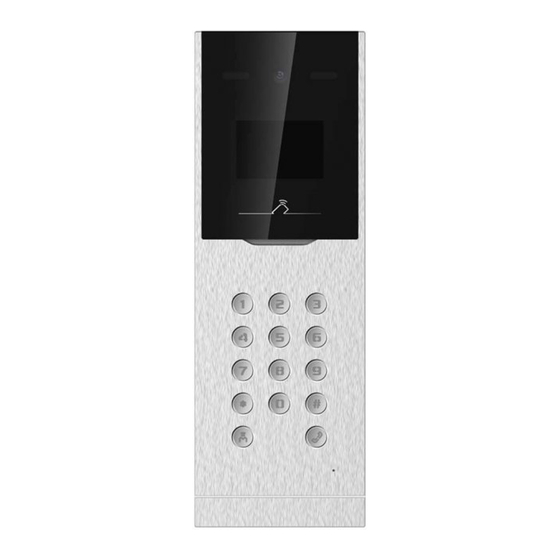
Video Intercom D Series Door Station User Manual 1 Appearance Description 1.1 Appearance of 80 Series Door Station Figure 1-1 Appearance of 80 Series Door Station Table 1-1 Descriptions Description Description IR Supplement Light Keypad Built-in Camera Call Button LCD Display Screen... -
Page 15: Appearance Of 81 Series Door Station
Video Intercom D Series Door Station User Manual 1.2 Appearance of 81 Series Door Station Figure 1-2 Appearance of 81 Series Door Station Table 1-2 Descriptions Descripiton Description Low Illumination Call Center Button Supplement Light Built-in Camera Microphone LCD Display Screen... -
Page 16: Appearance Of 30 Series Door Station
Video Intercom D Series Door Station User Manual Descripiton Description Keypad Loudspeaker Call Button TAMPER 1.3 Appearance of 30 Series Door Station Appearance of 30 Series Door Station Table 1-3 Descriptions Description Description Low Illumination Call Button Supplement Light Loudspeaker... - Page 17 Video Intercom D Series Door Station User Manual Description Description Card Reading Area TAMPER Keypad...
-
Page 18: Terminal And Wiring Description
Video Intercom D Series Door Station User Manual 2 Terminal and Wiring Description 2.1 Terminal Description Figure 2-1 Terminal Description Table 2-1 Descriptions Name Interface Description RESERVED RESERVED Network Interface ALARM IN SEN1 Door Contact Detection Input 1/Door Contact BTN1... - Page 19 Video Intercom D Series Door Station User Manual Name Interface Description 485A- Grounding LOCK1 Door Lock Relay Output (NO) COM1 Common Interface Door Lock Relay Output (NC) LOCK2 Door Lock Relay Output (NO) COM2 Common Interface Door Lock Relay Output (NC)
-
Page 20: Wiring Description
Video Intercom D Series Door Station User Manual Name Interface Description Reserved POWER 12 VDC DC 12 V Power Supply Input 2.2 Wiring Description 2.2.1 D-Series Door Lock Wiring Figure 2-2 Door Lock Wiring Note • Terminal NC1/COM1 is set as default for accessing electric bolt. Terminal NO1/ COM1 is set as default for accessing electric strike. -
Page 21: D-Series Exit Button Wiring (8081 Series)
Video Intercom D Series Door Station User Manual Figure 2-3 Door Contact Wiring Note Terminal SEN1/SEN2 can both connect to door contact. 2.2.3 D-Series Exit Button Wiring (8081 Series) -
Page 22: External Card Reader Wiring
Video Intercom D Series Door Station User Manual Figure 2-4 Exit Button Wiring Note Terminal BTN1/BTN2 can both connect to exit button. 2.2.4 External Card Reader Wiring Note • Please set the DIP switch first before connecting the card reader. - Page 23 Video Intercom D Series Door Station User Manual Description How to Configure OFF: RS-485 Set the Wiegand protocol (It is ON: Wiegand 26 invalid when setting OFF in 6.) OFF: Wiegand 34 RS-485 Card Reader Wiring Figure 2-5 RS-485 Card Reader Wiring...
-
Page 24: D-Series Elevator Controller Wiring
Video Intercom D Series Door Station User Manual Wiegand Card Reader Wiring Figure 2-6 Wiegand Card Reader Wiring 2.2.5 D-Series Elevator Controller Wiring Enter a short description of your concept here (optional). This is the start of your concept. 2.2.6 Alarm Input Device Wiring... -
Page 25: Alarm Output Device Wiring
Video Intercom D Series Door Station User Manual Figure 2-7 Alarm Input Wiring Diagram 2.2.7 Alarm Output Device Wiring The alarm output wiring diagram is as follows:... - Page 26 Video Intercom D Series Door Station User Manual Figure 2-8 Alarm Output Wiring Diagram...
-
Page 27: Installation
Video Intercom D Series Door Station User Manual 3 Installation • Make sure the device in the package is in good condition and all the assembly parts are included. • The power supply the door station support is 12 VDC. Please make sure your power supply matches your door station. - Page 28 Video Intercom D Series Door Station User Manual Figure 3-2 Drill an Installation Hole 2. Insert the gang box into the hole and fix it with 4 PA4 screws. Figure 3-3 Insert the Gang Box...
- Page 29 Video Intercom D Series Door Station User Manual 3. Make sure the edges of the gang box align to the wall and the hook A and hook B of the gang box hook onto the wall. 4. Route the cables of the door station through the cable hole.
-
Page 30: Installation Of 81 Series Door Station
Video Intercom D Series Door Station User Manual Figure 3-5 Fix the Door Station To install the door station onto the wall, you are required to use a matched gang box. Figure 3-6 Gang Box Note • The dimension of gang box is: 404 (W) × 123 (H) × 47.5 (D) mm. -
Page 31: Flush Mounting With Gang Box
Video Intercom D Series Door Station User Manual 3.2.2 Flush Mounting with Gang Box Steps 1. Drill a hole in the wal for inserting the gang box. The size of the hole should be larger than that of the gang box. The suggested size of the hole is 404.5 (W) ×... -
Page 32: Installation Of 30 Series Door Station
Video Intercom D Series Door Station User Manual 4. Put the door station into the gang box and hook the lock catches on the rear panel. Figure 3-9 Install the Door Station 5. Pull the door station downward and then push it towards the inside to make sure it fits the hole. -
Page 33: Gang Box Of 30 Series Door Station
Video Intercom D Series Door Station User Manual Figure 3-11 Gang Box Note • The dimension of gang box is: 343 (W) × 113 (H) × 55 (D) mm. • The dimensions above are for reference only. The actual size can be slightly different from the theoretical dimension. - Page 34 Video Intercom D Series Door Station User Manual Figure 3-12 Drill an Installation Hole 2. Insert the gang box into the hole and fix it with 4 PA4 screws. 3. Make sure the edges of the gang box align to the wall.
- Page 35 Video Intercom D Series Door Station User Manual Figure 3-13 Fix the Door Station...
-
Page 36: Activation
Video Intercom D Series Door Station User Manual 4 Activation 4.1 Activate Device Locally You are required to activate the device first by settings a strong password for it before you can use the device. Steps 1. Power on the device to enter the activation page automatically. -
Page 37: Activate Device Via Client Software
Video Intercom D Series Door Station User Manual Note • The password required 8 to 16 characters. • The way to enter the password, take button 2 as an example: Press 2 to enter the number '2' or hold 2 for 1.5 s and press 2 again to enter the character 'a'. -
Page 38: Activate Device Via Web
Video Intercom D Series Door Station User Manual Note • When the device is not activated, the basic operation and remote operation of device cannot be performed. • You can hold the Ctrl or Shift key to select multiple devices in the online devices, and click the Activate button to activate devices in batch. -
Page 39: Local Operation
Video Intercom D Series Door Station User Manual 5 Local Operation 5.1 Local Configuration 5.1.1 Edit Network Parameters After activating, you should edit the network parameters. Steps 1. Hold * and # at the same time to enter the authentication page. -
Page 40: Add Residents
Video Intercom D Series Door Station User Manual 5. After configuration, press * to save and exit. 5.1.3 Add Residents User Management You can add, edit and delete the informations of the users. Steps 1. Hold * and # at the same time to enter the authentication page. -
Page 41: Video Intercom Operation
Video Intercom D Series Door Station User Manual Steps 1. Hold * and # at the same time to enter the authentication page. 2. Authenticate via administrator. Authenticate face/card/fingerprint to login. Press # to enter the password to login. 3. Swritch to About according to the tips on the page. -
Page 42: Unlock Door
Video Intercom D Series Door Station User Manual 5.3 Unlock Door 5.3.1 Unlock by Password Unlock by Common Password Press any digit button on the main/sub door station page to enter the calling page. Enter 【 # + Common Password + #】to unlock the door. -
Page 43: Remote Configuration Via Web
Video Intercom D Series Door Station User Manual 6 Remote Configuration via Web 6.1 Live View In the browser address bar, enter the IP address of the device, and press the Enter key to enter the login page. Enter the user name and password and click Login to enter the Live View page. Or you can click Live View to enter the page. -
Page 44: Device Management
Video Intercom D Series Door Station User Manual • Check the box of the user and click Delete to delete the selected user. • Enter the keyword and click Search. The information will display in the list. 6.3 Device Management You can manage the linked device on the page. - Page 45 Video Intercom D Series Door Station User Manual the web browser. You can also set and view the saving paths of the captured pictures and recorded videos on the PC that running the web browser. Live View Parameters Stream Type Set the stream type as Main Stream or Sub-stream.
-
Page 46: System Settings
Video Intercom D Series Door Station User Manual 6.4.2 System Settings Follow the instructions below to configure the system settings, include System Settings, Maintenance, Security, and User Management, etc. Click System to enter the settings page. Basic Information Click System Settings → Basic Information to enter the settings page. On the page, you can edit Device Name and Device No. - Page 47 Video Intercom D Series Door Station User Manual Figure 6-2 Maintenance • Reboot: Click Reboot to reboot the device. • Restore Click Restore to reset all the parameters, except the IP parameters and user information, to the default settings. Default Click Default to restore all parameters to default settings.
-
Page 48: Network Settings
Video Intercom D Series Door Station User Manual Note We highly recommend you to create a strong password of your own choosing (using a minimum of 8 characters, including at least three kinds of following categories: upper case letters, lower case letters, numbers, and special characters) in order to increase the security of your product. - Page 49 Video Intercom D Series Door Station User Manual Figure 6-4 TCP/IP Settings 2. Configure the network parameters. Check DHCP, the device will get the parameters automatically. Set the IPv4 Address, IPv4 Subnet Mask and IPv4 Default Gateway manually. 3. Configure the DNS server.
- Page 50 Video Intercom D Series Door Station User Manual The default port number is 554 and it can be changed to any port No. ranges from 1 to 65535. Server Port The default server port number is 8000, and it can be changed to any port No.
- Page 51 Video Intercom D Series Door Station User Manual Figure 6-6 SNMP Settings 2. Check the checkbox of Enable SNMPv1, Enable SNMP v2c, Enable SNMPv3 to enable the feature correspondingly. 3. Configure the SNMP settings. 4. Click Save to enable the settings.
- Page 52 Video Intercom D Series Door Station User Manual Steps 1. Click Network → Advanced Settings → FTP to enter the settings page. Figure 6-7 FTP Settings 2. Check Enable FTP. 3. Select Server Type. 4. Input the Server IP Address and Port.
-
Page 53: Video & Audio Settings
Video Intercom D Series Door Station User Manual 6.4.4 Video & Audio Settings Video Parameters Steps 1. Click Video/Audio → Video to enter the settings page. Figure 6-8 Video Parameters 2. Select the Stream Type. 3. Configure the video parameters. - Page 54 Video Intercom D Series Door Station User Manual Select the resolution of the video output. Bitrate Type Select the bitrate type to constant or variable. Video Quality When bitrate type is selected as Variable, 6 levels of video quality are selectable.
-
Page 55: Display Settings
Video Intercom D Series Door Station User Manual Stream Type Select the stream type to main stream or sub stream. Audio Encoding The device support G.711ulaw and G.711 alaw. 3. Adjust the Input Volume, Output Volume and Speak Volume. Note Available range of volume: 0 to 10. -
Page 56: Event Settings
Video Intercom D Series Door Station User Manual Brightness describes bright of the image, which ranges from 1 to 100. Contrast Contrast describes the contrast of the image, which ranges from 1 to 100. Saturation Saturation describes the colorfulness of the image color, which ranges from 1 to 100. - Page 57 Video Intercom D Series Door Station User Manual Figure 6-11 Motion Detection 2. Check Enable Motion Detection to enable the function. 3. Click Draw Area.Click and drag the mouse on the live video to draw a motion detection area. Click Stop Drawing to finish drawing one area. Click Save to save the settings.
- Page 58 Video Intercom D Series Door Station User Manual Notify Surveillance Center Send an exception or alarm signal to the remote management software when an event occurs. 7. Click Save to enable the settings. Set Video Tampering Alarm When the configured area is covered and cannot be monitored normally, the alarm is triggered and the device takes certain alarm response actions.
-
Page 59: Intercom Settings
Video Intercom D Series Door Station User Manual Figure 6-12 Event Linkage 2. Select the Major Type as Device Event or Door Event. 3. Select the type of the Normal Linkage for the event. 4. Click Save to enable the settings. - Page 60 • For main door station (D series or V series), the serial No. is 0. • For sub door station (D series or V series), the serial No. cannot be 0. Serial No. ranges from 1 to 99. • For each villa or building, at least one main door station (D series or V series) should be configured, and one sub door stations (D series or V series) can be customized.
-
Page 61: Access Control Settings
Video Intercom D Series Door Station User Manual Figure 6-14 Linked Network Settings 2. Set the master station IP address and master station SIP cllient Port. 3. Set the private SIP server IP address and private SIP Server Port. 4. Set the SIP Client Port. - Page 62 Video Intercom D Series Door Station User Manual Permission Password Steps 1. Click Access Control → Permission Password to enter the settings page. Figure 6-15 Permission Password 2. Select the password type. 3. Change the password. 4. Set the number of doorphone.
- Page 63 Video Intercom D Series Door Station User Manual 2. Select the door and edit the door name. 3. Set door contact status. 4. Set lock action time. 5. Click Save to enable the settings. Card Security Click Access Control → Card Security to enter the settings page.
- Page 64 Video Intercom D Series Door Station User Manual Figure 6-17 Elevator Control 2. Check to enable elevator control function. 3. Select an Elevator No., and select an elevator controller type for the elevator. 4. Set the Negative Floor. 5. Select the Interface Type as RS-485 or Network Interface. And enable the elevator control.
- Page 65 Video Intercom D Series Door Station User Manual RS-485 Settings Set the working mode to linked device. Steps 1. Click Access Control → RS485 Settings to enter the settings page. Figure 6-18 RS-485 Settings 2. Select the No. 3. Select the working mode.
-
Page 66: Configuration Via Client Software
Video Intercom D Series Door Station User Manual 7 Configuration via Client Software 7.1 Edit Network Parameters To operate and configure the device via LAN (Local Area Network), you need connect the device in the same subnet with your PC. You can edit network parameters via iVMS-4200 client software. -
Page 67: Add Device By Ip Address
Video Intercom D Series Door Station User Manual Figure 7-1 Add to the Client 7.2.2 Add Device by IP Address Steps 1. Click +Add to pop up the adding devices dialog box. 2. Select IP/Domain as Adding Mode. 3. Enter corresponding information. -
Page 68: Remote Configuration
Video Intercom D Series Door Station User Manual You can add many devices at once whose IP addresses are among the IP segment. Steps 1. Click +Add to pop up the dialog box. 2. Select IP Segment as Adding Mode. -
Page 69: Modify And Delete Organization
Video Intercom D Series Door Station User Manual Note Up to 10 levels of organizations can be created. 7.5.2 Modify and Delete Organization You can select the added organization and click to modify its name. You can select an organization, and click X button to delete it. - Page 70 Video Intercom D Series Door Station User Manual 1) Enter basic information: name, gender, tel, birthday details, effective period and email address. Note The length of person name should be less than 15 characters. 2) Click Add face to upload the photo.
-
Page 71: Modify And Delete Person
Video Intercom D Series Door Station User Manual 7.6.2 Modify and Delete Person Select the person and click Edit to open the editing person dialog. To delete the person, select a person and click Delete to delete it. Note If a card is issued to the current person, the linkage will be invalid after the person is deleted. -
Page 72: Change Person To Other Organization
Video Intercom D Series Door Station User Manual Steps Note This function is only supported by the device the connection mothod of which is TCP/IP when adding the device. 1. In the organization list on the left, click to select an organization to import the persons. -
Page 73: Issue Card In Batch
Video Intercom D Series Door Station User Manual Enter the result of your step here (optional). Example Enter an example that illustrates the current task (optional). What to do next Enter the tasks the user should do after finishing this task (optional). -
Page 74: Permission Settings
Video Intercom D Series Door Station User Manual Figure 7-3 Card Settings 3. Select Card Type and Card No. Type. 4. Click OK to save the settings. Result After issuing the card to the person, the person and card information will display in the Person(s) with Card Issued list. -
Page 75: Video Intercom Settings
Video Intercom D Series Door Station User Manual 2) Select the Template of the schedule. 3) Check the person to Selected according to your needs. 4) Check the device to Selected according to your needs. 4. Click Save. 5. Check the permission and click Apply All to Device. -
Page 76: Live View Via Door Station
Video Intercom D Series Door Station User Manual • Click to adjust the volume of the loudspeaker. • Click to adjust the volume of the microphone. • Click Hang Up to hang up the dialog. • Click to open the door remotely. -
Page 77: Search Video Intercom Information
Video Intercom D Series Door Station User Manual 4. Edit the Subject, Type and Information. 5. Click View to select the picture. 6. Click Send. Note • Up to 63 characters are allowed in the Subject field. • Up to 6 pictures in the JPGE format can be added to one notice. And the maximum size of one picture is 512KB. - Page 78 Video Intercom D Series Door Station User Manual Click ˅ to unfold the drop-down list and select the device type as Indoor Station, Door Station, Outer Door Station or Analog Indoor Station. Or select All Devices to search logs with all device types.
-
Page 79: Communication Matrix And Device Command
A. Communication Matrix and Device Command Communication Matrix Scan the following QR code to get the device communication matrix. Note that the matrix contains all communication ports of Hikvision access control and video intercom devices. Figure A-1 QR Code of Communication Matrix Device Command Scan the following QR code to get the device common serial port commands. - Page 80 UD19922B...
Need help?
Do you have a question about the D Series and is the answer not in the manual?
Questions and answers