Advertisement
Table of Contents
- 1 Table of Contents
- 2 Warning Decal Placement
- 3 Important Precautions
- 4 Before You Begin
- 5 Part Identification Chart
- 6 Assembly
- 7 How to Use the Exercise Bike
- 8 How to Use the Console
- 9 Maintenance and Troubleshooting
- 10 Exercise Guidelines
- 11 Part List
- 12 Exploded Drawing
- 13 Ordering Replacement Parts
- 14 Recycling Information
- Download this manual
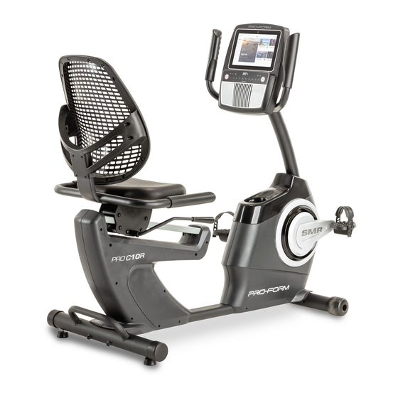
Model No. PFEX73921-INT.0
Serial No.
Write the serial number in the space
above for reference.
Serial
Number
Decal
MEMBER CARE
UNITED KINGDOM
Website: iconsupport.eu
E-mail: csuk@iconeurope.com
Write:
ICON Health & Fitness, Ltd.
Unit 4, Westgate Court
Silkwood Park
OSSETT
WF5 9TT
UNITED KINGDOM
AUSTRALIA
Call: 1800 993 770
E-mail: australiacc@iconfitness.com
Write:
iFIT Inc.
PO Box 635
WINSTON HILLS NSW 2153
AUSTRALIA
CAUTION
Read all precautions and
instructions in this manual before
using this equipment. Keep this
manual for future reference.
USER'S MANUAL
iconeurope.com
Advertisement
Table of Contents

Related Manuals for Pro-Form PRO C10R


Summary of Contents for Pro-Form PRO C10R
- Page 1 Model No. PFEX73921-INT.0 Serial No. Write the serial number in the space USER’S MANUAL above for reference. Serial Number Decal MEMBER CARE UNITED KINGDOM Website: iconsupport.eu E-mail: csuk@iconeurope.com Write: ICON Health & Fitness, Ltd. Unit 4, Westgate Court Silkwood Park OSSETT WF5 9TT UNITED KINGDOM...
-
Page 2: Table Of Contents
TABLE OF CONTENTS WARNING DECAL PLACEMENT ............. . .2 IMPORTANT PRECAUTIONS . -
Page 3: Important Precautions
IMPORTANT PRECAUTIONS WARNING: To reduce the risk of serious injury, read all important precautions and instructions in this manual and all warnings on your exercise bike before using your exercise bike. iFIT assumes no responsibility for personal injury or property damage sustained by or through the use of this product. -
Page 4: Before You Begin
The ing endurance, and toning the body. The PRO C10R model number and the location of the serial number exercise bike provides a selection of features designed decal are shown on the front cover of this manual. -
Page 5: Part Identification Chart
PART IDENTIFICATION CHART Use the drawings below to identify the small parts needed for assembly. The number in parentheses below each drawing is the key number of the part, from the PART LIST near the end of this manual. The number following the key number is the quantity needed for assembly. -
Page 6: Assembly
ASSEMBLY • Assembly requires two persons. In addition to the included tool(s), assembly requires the following tools: • Place all parts in a cleared area and remove the one Phillips screwdriver packing materials. Do not dispose of the packing materials until you fi nish all assembly steps. one standard screwdriver •... - Page 7 2. Orient the Rear Stabilizer (3) as shown. While a second person lifts the rear of the Frame (1), attach the Rear Stabilizer (3) to the Frame with two M10 x 80mm Screws (21). 3. Orient the Front Stabilizer (2) as indicated by the sticker.
- Page 8 4. Orient the Adjustment Lever (6) as shown. Attach the Adjustment Lever (6) to the Brake Axle (37) with two M6 x 16mm Screws (33), two M6 Split Washers (34), and two M6 Washers (35). 5. Attach the Seat Frame (9) to the Seat Carriage (7) with four M8 x 40mm Screws (28);...
- Page 9 6. Attach the Seat (10) to the Seat Frame (9) with four M6 x 16mm Screws (33) (only two Screws are shown); start all the Screws, and then tighten them. 7. Slide the Backrest Frame (8) onto the Seat Frame (9). Attach the Backrest Frame (8) with four M6 x 30mm Screws (41) and four M6 Washers (35);...
- Page 10 8. Remove the Accessory Tray (5) from the Left and Right Front Shields (57, 58). Set the Accessory Tray aside. Tip: It may be necessary to use a standard screwdriver to release the tabs on the Accessory Tray. Have a second person hold the Upright (4) near the Frame (1).
- Page 11 10. Untie and discard the wire tie on the Main Wire (31). While a second person holds the Handlebar (14) near the Upright (4), route the Main Wire (31) through the notch (B) in the Upright and through the hole (C) in the Handlebar. Tip: Avoid pinching the Main Wire (31).
- Page 12 12. Slide the Console Cover (16) upward against the Handlebar (14). Attach the Console Cover with two M4 x 16mm Screws (49). 13. Identify the Right Pedal (13). Using your fingers, turn the Right Pedal about halfway into the Right Crank Arm (71).
- Page 13 14. Plug the Power Adapter (50) into the receptacle on the front of the exercise bike. Note: To plug the Power Adapter (50) into an outlet, see HOW TO PLUG IN THE POWER ADAPTER on page 14. 15. After the exercise bike is assembled, inspect it to make sure that it is assembled correctly, that it functions properly, and that all parts are properly tightened.
-
Page 14: How To Use The Exercise Bike
HOW TO USE THE EXERCISE BIKE HOW TO PLUG IN THE POWER ADAPTER HOW TO ADJUST THE SEAT IMPORTANT: If the exercise bike has been exposed The seat can be to cold temperatures, allow it to warm to room tem- adjusted forward perature before you plug in the power adapter (A). - Page 15 HOW TO LEVEL THE EXERCISE BIKE THE OPTIONAL TABLET HOLDER If the exercise bike The optional tablet rocks slightly on your holder (F) will hold floor during use, your tablet securely turn one or both of in place and enable the leveling feet (E) you to use your tablet under the rear stabi-...
-
Page 16: How To Use The Console
HOW TO USE THE CONSOLE CONSOLE DIAGRAM FEATURES OF THE CONSOLE When you use the manual mode of the console, you can change the resistance of the pedals with the touch The advanced console offers an array of features of a button. designed to make your workouts more effective and enjoyable. - Page 17 HOW TO TURN ON THE CONSOLE HOW TO SET UP THE CONSOLE The included power adapter must be used to operate Before you use the exercise bike for the first time, set the exercise bike. See HOW TO PLUG IN THE up the console.
- Page 18 HOW TO USE THE MANUAL MODE Touch the various workout information displays to view more options. Touch the more button 1. Touch the screen or press any button on the (+ symbol) to view statistics or charts. Touch the console to turn on the console. screen in any open space to view even more dis- play mode options.
- Page 19 6. Turn on the fan if desired. 3. Select a workout. The fan has several speed To select a workout from the home screen or the settings, including an auto workout library, simply touch the desired workout mode. While the auto mode button on the screen.
- Page 20 If the resistance level is too high or too low, you To end the workout session, touch the screen, can manually override the setting by pressing the touch the pause option, and then follow the Resistance buttons (see step 3 on page 18). prompts on the screen to end the workout and return to the home screen.
- Page 21 HOW TO CREATE A DRAW-YOUR-OWN-MAP If you make a mistake, touch Undo in the map WORKOUT options. 1. Touch the screen or press any button on the The screen will display the elevation and distance console to turn on the console. statistics for your workout.
- Page 22 HOW TO USE AN IFIT WORKOUT 4. Select an iFIT workout from the home screen or the workout library. To use an iFIT workout, you must be logged into your iFIT account (see step 3 below) and the console Touch the buttons at the bottom of the screen to must be connected to a wireless network (see HOW select either the home screen (Home button) or the TO CONNECT TO A WIRELESS NETWORK on...
- Page 23 6. Create a list of favorite iFIT workouts if desired. THE OPTIONAL HEART RATE MONITOR To mark an iFIT workout as a favorite, simply view Whether your the overview or workout summary of the desired goal is to iFIT workout and touch the favorites button (heart burn fat or to symbol).
- Page 24 HOW TO CHANGE CONSOLE SETTINGS Equipment • Equipment Info IMPORTANT: Firmware updates are always • Equipment Settings designed to improve your exercise experience. As a • Maintenance result, new settings and features may not be described • Wi-Fi in this manual. Take time to explore the console to learn how new settings and features work.
- Page 25 The screen will show the progress of the update. 3. Enable Wi-Fi. When the update is complete, the console will turn off and then turn back on. If it does not, unplug the Make sure that Wi-Fi ® is enabled. If it is not power adapter, wait for several seconds, and then enabled, touch the Wi-Fi toggle to enable it.
-
Page 26: Maintenance And Troubleshooting
MAINTENANCE AND TROUBLESHOOTING MAINTENANCE If a replacement power adapter is needed, call the telephone number on the front cover of this man- Regular maintenance is important for optimal ual. IMPORTANT: To avoid damaging the console, performance and to reduce wear. Inspect and properly use only a manufacturer-supplied regulated power tighten all parts each time the exercise bike is used. - Page 27 HOW TO ADJUST THE REED SWITCH Next, rotate the Pulley (75) until a Magnet (67) is aligned with the Reed Switch (18). Slide the Reed If the console does not display correct feedback, the Switch slightly toward or away from the Magnet. Then, reed switch should be adjusted.
-
Page 28: Exercise Guidelines
EXERCISE GUIDELINES Aerobic Exercise—If your goal is to strengthen your WARNING: cardiovascular system, you must perform aerobic Before beginning this exercise, which is activity that requires large amounts or any exercise program, consult your physi- of oxygen for prolonged periods of time. For aerobic cian. -
Page 29: Part List
PART LIST Model No. PFEX73921-INT.0 R1121A Key No. Qty. Description Key No. Qty. Description Frame Lever Handle Front Stabilizer M6 x 30mm Screw Rear Stabilizer M8 x 20mm Screw Upright M6 x 13mm Screw Accessory Tray Upper Roller Adjustment Lever Lower Roller Seat Carriage Roller Axle... -
Page 30: Exploded Drawing
EXPLODED DRAWING A Model No. PFEX73921-INT.0 R1121A... - Page 31 EXPLODED DRAWING B Model No. PFEX73921-INT.0 R1121A...
-
Page 32: Ordering Replacement Parts
ORDERING REPLACEMENT PARTS To order replacement parts, please see the front cover of this manual. To help us assist you, be prepared to provide the following information when contacting us: • the model number and serial number of the product (see the front cover of this manual) •...
Need help?
Do you have a question about the PRO C10R and is the answer not in the manual?
Questions and answers
The seat adjuster doesn’t lock the seat,
To fix the seat adjuster on the Pro-Form PRO C10R that doesn't lock the seat, check the Adjustment Lever (6) and ensure it is properly attached to the Brake Axle (37) with two M6 x 16mm Screws (33), two M6 Split Washers (34), and two M6 Washers (35). Tighten all screws securely. If the problem persists, inspect the Seat Frame (9) and Seat Carriage (7) connections to ensure they are properly secured with the M8 x 40mm Screws (28).
This answer is automatically generated
Looking for part number and price for proform C10R bike console main wiring harness that plugs into the main harness from power.