Advertisement
Table of Contents
- 1 Table of Contents
- 2 Warning Decal Placement
- 3 Important Precautions
- 4 Before You Begin
- 5 Part Identification Chart
- 6 Assembly
- 7 How to Use the Exercise Bike
- 8 How to Use the Console
- 9 Maintenance and Troubleshooting
- 10 Exercise Guidelines
- 11 Part List
- 12 Exploded Drawing
- 13 Ordering Replacement Parts
- 14 Recycling Information
- Download this manual
Model No. PFEX17820-INT.0
Serial No.
Write the serial number in the space
above for reference.
Serial Number
CUSTOMER SERVICE
UNITED KINGDOM
Call: 0330 123 1045
From Ireland: 053 92 36102
Website: iconsupport.eu
E-mail: csuk@iconeurope.com
Write:
ICON Health & Fitness, Ltd.
Unit 4, Westgate Court
Silkwood Park
OSSETT
WF5 9TT
UNITED KINGDOM
AUSTRALIA
Call: 1800 993 770
E-mail: australiacc@iconfitness.com
Write:
ICON Health & Fitness, Inc.
PO Box 635
WINSTON HILLS NSW 2153
AUSTRALIA
CAUTION
Read all precautions and
instructions in this manual before
using this equipment. Keep this
manual for future reference.
Decal
USER'S MANUAL
iconeurope.com
Advertisement
Table of Contents

Related Manuals for Pro-Form PROC10 U


Summary of Contents for Pro-Form PROC10 U
- Page 1 Model No. PFEX17820-INT.0 Serial No. USER’S MANUAL Write the serial number in the space above for reference. Serial Number Decal CUSTOMER SERVICE UNITED KINGDOM Call: 0330 123 1045 From Ireland: 053 92 36102 Website: iconsupport.eu E-mail: csuk@iconeurope.com Write: ICON Health & Fitness, Ltd. Unit 4, Westgate Court Silkwood Park OSSETT...
-
Page 2: Table Of Contents
TABLE OF CONTENTS WARNING DECAL PLACEMENT ............. . .2 IMPORTANT PRECAUTIONS . -
Page 3: Important Precautions
IMPORTANT PRECAUTIONS WARNING: To reduce the risk of serious injury, read all important precautions and instructions in this manual and all warnings on the exercise bike before using the exercise bike. ICON assumes no responsibility for personal injury or property damage sustained by or through the use of this product. -
Page 4: Before You Begin
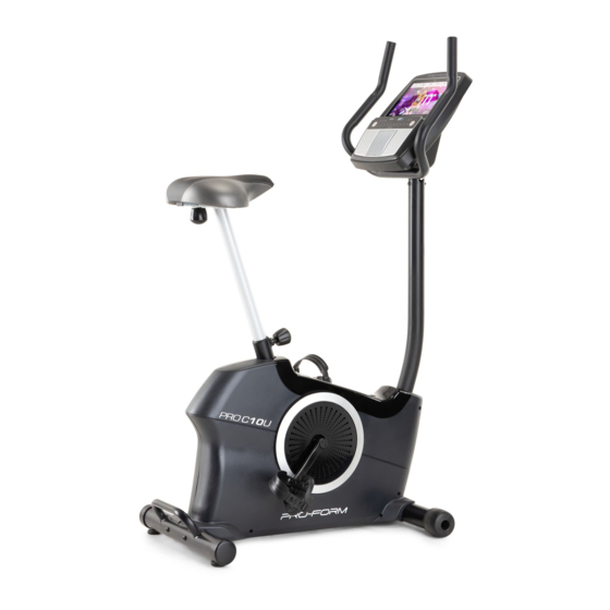
BEFORE YOU BEGIN ® Thank you for selecting the revolutionary PROFORM reading this manual, please see the front cover of this PRO C10 U exercise bike. Cycling is one of the most manual. To help us assist you, note the product model effective exercises for increasing cardiovascular fit- number and serial number before contacting us. -
Page 5: Part Identification Chart
PART IDENTIFICATION CHART Use the drawings below to identify the small parts needed for assembly. The number in parentheses below each drawing is the key number of the part, from the PART LIST near the end of this manual. The number following the key number is the quantity needed for assembly. -
Page 6: Assembly
ASSEMBLY • Assembly requires two persons. • In addition to the included tool(s), assembly requires the following tools: • Place all parts in a cleared area and remove the one Phillips screwdriver packing materials. Do not dispose of the packing materials until you fi... - Page 7 3. Set a sturdy piece of packing material under the front of the Frame (1). Attach the Front Stabilizer (2) to the Frame (1) with two M10 x 98mm Screws (53). Then, remove the packing material. 4. Raise the Upright (4) to the vertical position. Have a second person hold the Upright until you complete this step.
- Page 8 5. Attach the Front Shield Cover (9) to the Rear Shield Cover (7) with an M4 x 16mm Flat Head Screw (93). Then, attach the Accessory Tray (8) to the Upright (4) with an M6 x 50mm Screw (89). 6. Identify the Left Armrest (31). Attach the Left Armrest (31) to the Handlebar (5) with two M4 x 22mm Screws (84).
- Page 9 7. Have a second person hold the Handlebar (5) near the Upright (4). See the inset drawing. Route the Upper Wire (87) through the Pivot Post (78) and the Pivot Bracket (71) as shown. Tip: It may be easier to route the Upper Wire if you adjust the angle of the Pivot Bracket by turning the Console Knob (77).
- Page 10 9. Press the Front Pivot Cover (12) and the Rear Pivot Cover (15) together around the Pivot Bracket (71). Attach the Front and Rear Pivot Covers (12, 15) to the Pivot Bracket (71) with two M4 x 22mm Screws (84). 10.
- Page 11 11. Loosen the Seat Post Knob (27) and pull it out- ward. Then, remove and discard the shipping bracket (not shown) that is inside the Seat Post Sleeve (28). Next, insert the Seat Post (6) into the Seat Post Sleeve (28), and release the Seat Post Knob (27).
- Page 12 13. Plug the Power Adapter (67) into the receptacle on the frame of the exercise bike. Note: To plug the Power Adapter (67) into an outlet, see HOW TO PLUG IN THE POWER ADAPTER on page 13. 14. After the exercise bike is assembled, inspect it to make sure that it is assembled correctly, that it func- tions properly, and that all parts are properly tightened.
-
Page 13: How To Use The Exercise Bike
HOW TO USE THE EXERCISE BIKE HOW TO PLUG IN THE POWER ADAPTER HOW TO ADJUST THE LATERAL POSITION OF THE SEAT IMPORTANT: If the exercise bike has been exposed to cold temperatures, allow it to warm to room tem- To adjust the lateral perature before you plug in the power adapter (A). - Page 14 HOW TO ADJUST THE CONSOLE THE OPTIONAL TABLET HOLDER The console can be The optional tab- adjusted to several let holder (G) will angles. To adjust hold your tablet the console, turn the securely in place console knob (F) and enable you until the console is to use your tablet at the desired angle.
-
Page 15: How To Use The Console
HOW TO USE THE CONSOLE CONSOLE DIAGRAM FEATURES OF THE CONSOLE When you use the manual mode of the console, you can change the resistance of the pedals with the touch The advanced console offers an array of features of a button. designed to make your workouts more effective and enjoyable. - Page 16 HOW TO TURN ON THE CONSOLE HOW TO USE THE TOUCH SCREEN The included power adapter must be used to oper- The console features a tablet with a full-color touch ate the exercise bike. See HOW TO PLUG IN THE screen.
- Page 17 HOW TO SET UP THE CONSOLE To change console settings, see page 24. To connect to a wireless network, see page 25. To Before you use the exercise bike for the first time, set use the sound system, see page 27. up the console.
- Page 18 4. Follow your progress. If this model does not include a compatible heart rate monitor, see page 26 for The console offers several display modes. The information about ordering one. display mode that you select will determine which workout information is shown. The console will connect to your compatible heart rate monitor automatically.
- Page 19 HOW TO USE A FEATURED WORKOUT To draw your own map for a workout, see HOW TO CREATE A DRAW-YOUR-OWN-MAP WORKOUT 1. Touch the screen or press any button on the on page 21. console to turn on the console. When you select a workout, the screen will show See HOW TO TURN ON THE CONSOLE on an overview of the workout that includes details...
- Page 20 Note: The calorie goal is an estimate of the 5. Follow your progress. number of calories that you will burn during the workout. The actual number of calories that you See step 4 on page 18. burn will depend on various factors such as your weight.
- Page 21 HOW TO CREATE A DRAW-YOUR-OWN-MAP If you make a mistake, touch Undo in the map WORKOUT options. 1. Touch the screen or press any button on the The screen will display the elevation and distance console to turn on the console. statistics for your workout.
- Page 22 HOW TO USE AN IFIT WORKOUT 4. Select an iFit workout from the home screen or the workout library. To use an iFit workout, you must be logged into your iFit account (see step 3 below) and the console Touch the buttons at the bottom of the screen to must be connected to a wireless network (see HOW select either the home screen (Home button) or the TO CONNECT TO A WIRELESS NETWORK on...
- Page 23 6. Create a list of favorite iFit workouts if desired. 9. Wear a compatible heart rate monitor and measure your heart rate if desired. To mark an iFit workout as a favorite, simply view the overview or workout summary of the desired See step 5 on page 18.
- Page 24 HOW TO CHANGE CONSOLE SETTINGS 3. Customize the unit of measurement and other settings. IMPORTANT: Some of the settings and features described may not be enabled. Occasionally, a To customize the unit of measurement, the time firmware update may cause your console to function zone, or other settings, touch Equipment Info or slightly differently.
- Page 25 6. Calibrate the incline system. HOW TO CONNECT TO A WIRELESS NETWORK To calibrate the incline system, touch Maintenance, To use iFit workouts and to use several other features touch Calibrate Incline, and then touch Begin. The of the console, the console must be connected to a exercise bike will automatically rise to the maxi- wireless network.
- Page 26 Note: You must have your own wireless network THE OPTIONAL HEART RATE MONITOR and an 802.11b/g/n router with SSID broadcast enabled (hidden networks are not supported). Whether your goal is to When a list of networks appears, touch the desired burn fat or to network.
- Page 27 HOW TO USE THE SOUND SYSTEM Note: The console can save 8 devices in its memory. If you have previously paired your device Connect with an Audio Cable to the console, you can simply press the Bluetooth If the console has an audio jack, you can connect an Audio button to connect your device to the console.
-
Page 28: Maintenance And Troubleshooting
MAINTENANCE AND TROUBLESHOOTING MAINTENANCE HOW TO ADJUST THE DRIVE BELT Regular maintenance is important for optimal If the pedals slip while you are pedaling, even while the performance and to reduce wear. Inspect and properly resistance is adjusted to the highest setting, the drive tighten all parts each time the exercise bike is used. - Page 29 HOW TO ADJUST THE REED SWITCH Next, locate the Reed Switch (57). Rotate the Left Crank Arm (20) until a Magnet (55) is aligned with the If the console does not display correct feedback, the Reed Switch. Then, loosen the M5 x 16mm Flat Head reed switch should be adjusted.
-
Page 30: Exercise Guidelines
EXERCISE GUIDELINES Aerobic Exercise—If your goal is to strengthen your WARNING: cardiovascular system, you must perform aerobic Before beginning this exercise, which is activity that requires large amounts or any exercise program, consult your physi- of oxygen for prolonged periods of time. For aerobic cian. - Page 31 SUGGESTED STRETCHES The correct form for several basic stretches is shown at the right. Move slowly as you stretch; never bounce. 1. Toe Touch Stretch Stand with your knees bent slightly and slowly bend forward from your hips. Allow your back and shoulders to relax as you reach down toward your toes as far as possible.
-
Page 32: Part List
PART LIST Model No. PFEX17820-INT.0 R0321A Key No. Qty. Description Key No. Qty. Description Frame M8 Locknut Front Stabilizer M8 x 12mm Screw Rear Stabilizer Idler Upright M8 Black Split Washer Handlebar Resistance Motor Seat Post M8 x 18mm Screw Rear Shield Cover Knob Nut Accessory Tray... - Page 33 Key No. Qty. Description Key No. Qty. Description M5 x 12mm Screw M8 x 12mm x 1.5mm Washer M5 x 21mm Screw M8 x 12mm x 4.5mm Washer Upper Wire M4 x 16mm Flat Head Screw Grommet – User’s Manual M6 x 50mm Screw –...
-
Page 34: Exploded Drawing
EXPLODED DRAWING A Model No. PFEX17820-INT.0 R0321A 43 61... - Page 35 EXPLODED DRAWING B Model No. PFEX17820-INT.0 R0321A...
-
Page 36: Ordering Replacement Parts
ORDERING REPLACEMENT PARTS To order replacement parts, please see the front cover of this manual. To help us assist you, be prepared to provide the following information when contacting us: • the model number and serial number of the product (see the front cover of this manual) •...
Need help?
Do you have a question about the PROC10 U and is the answer not in the manual?
Questions and answers