Table of Contents
Advertisement
Model No. PFEX39420-INT.0
Serial No.
Write the serial number in the space
above for reference.
Serial
Number
Decal
CUSTOMER SERVICE
UNITED KINGDOM
Call: 0330 123 1045
From Ireland: 053 92 36102
Website: iconsupport.eu
E-mail: csuk@iconeurope.com
Write:
ICON Health & Fitness, Ltd.
Unit 4, Westgate Court
Silkwood Park
OSSETT
WF5 9TT
UNITED KINGDOM
AUSTRALIA
Call: 1800 993 770
E-mail: australiacc@iconfitness.com
Write:
ICON Health & Fitness, Inc.
PO Box 635
WINSTON HILLS NSW 2153
AUSTRALIA
CAUTION
Read all precautions and
instructions in this manual before
using this equipment. Keep this
manual for future reference.
USER'S MANUAL
iconeurope.com
Advertisement
Table of Contents

Related Manuals for Pro-Form TOUR DE FRANCE CBC


Summary of Contents for Pro-Form TOUR DE FRANCE CBC
- Page 1 Model No. PFEX39420-INT.0 Serial No. USER’S MANUAL Write the serial number in the space above for reference. Serial Number Decal CUSTOMER SERVICE UNITED KINGDOM Call: 0330 123 1045 From Ireland: 053 92 36102 Website: iconsupport.eu E-mail: csuk@iconeurope.com Write: ICON Health & Fitness, Ltd. Unit 4, Westgate Court Silkwood Park OSSETT...
-
Page 2: Table Of Contents
TABLE OF CONTENTS WARNING DECAL PLACEMENT ............. . .2 IMPORTANT PRECAUTIONS . -
Page 3: Important Precautions
IMPORTANT PRECAUTIONS WARNING: To reduce the risk of serious injury, read all important precautions and instructions in this manual and all warnings on your exercise bike before using your exercise bike. ICON assumes no responsibility for personal injury or property damage sustained by or through the use of this product. -
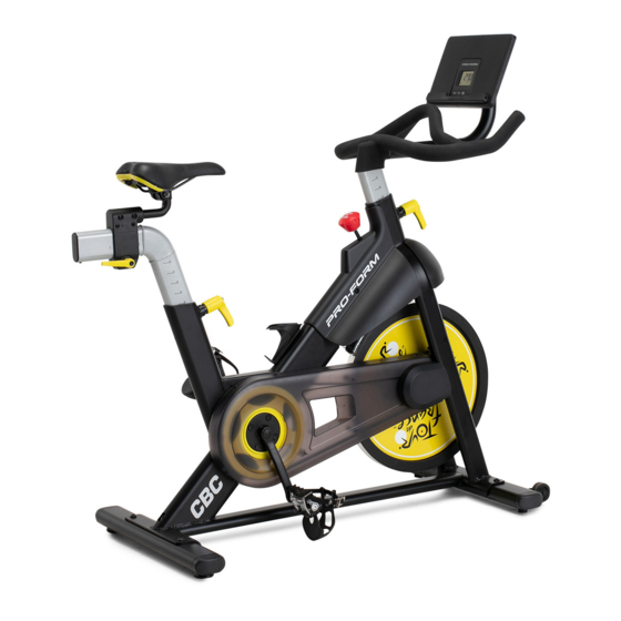
Page 4: Before You Begin
The model number and the location of the serial number LE TOUR DE FRANCE CBC exercise bike provides a decal are shown on the front cover of this manual. selection of features designed to make your workouts at home more effective and enjoyable. -
Page 5: Part Identification Chart
PART IDENTIFICATION CHART Use the drawings below to identify the small parts needed for assembly. The number in parentheses below each drawing is the key number of the part, from the PART LIST near the end of this manual. The number following the key number is the quantity needed for assembly. -
Page 6: Assembly
ASSEMBLY • Assembly requires two persons. one Phillips screwdriver • Place all parts in a cleared area and remove the one adjustable wrench packing materials. Do not dispose of the packing materials until you finish all assembly steps. one rubber mallet •... - Page 7 2. If there are shipping tubes (not shown) attached to the front and rear of the Frame (1), remove and discard the shipping tubes and the hardware attaching them. Orient the Front Stabilizer (2) as shown, and attach it to the Frame (1) with two M10 x 25mm Screws (69).
- Page 8 4. Tip: See the inset drawing to learn how to operate the Adjustment Handle (14). Loosen handle Locate the Adjustment Handle (14) on the rear of the Frame (1). Pull the Adjustment Handle Pull handle outward, and insert the Saddle Post (7) into the Frame.
- Page 9 6. Have a second person hold the Handlebar (4) near the Frame (1). Loosen handle Next, locate the wire tie (A) in the Frame (1). Tie the wire tie to the Upper Wire (90) in the Handlebar (4). Then, pull the lower end of the Pull wire tie until the Upper Wire is routed through handle...
- Page 10 7. See the inset drawing. Connect the connector on the Upper Wire (90) to the connector on the Lower Wire (82). Next, tighten the zip tie (C) around the indicated mark (D) on the Upper Wire (90). Then, cut off the excess zip tie.
- Page 11 9. Untie the wire tie (E) holding the Upper Wire (90) to the Handlebar (4). While a second person holds the Console Mount (5) near the Handlebar (4), connect the Extension Wire (12) in the Console Mount to the Upper Wire (90) in the Handlebar (4). Tip: Avoid pinching the wires.
- Page 12 11. Orient the Console Housing (86) and the Console Deck (89) as shown. Attach the Console Housing (86) to the Console Deck (89) with four M4 x 16mm Screws (11); start all the Screws, and then tighten them. 12. While a second person holds the Console Deck (89) near the Console Mount (5), connect the Console Wire (J) to the Extension Wire (12).
- Page 13 13. Tip: Avoid pinching the wires. If necessary, tilt the Console Bracket (26) upward to make Avoid pinching this step easier. Attach the Console Deck (89) the wires to the Console Bracket with four M4 x 12mm Screws (81); start all the Screws, and then tighten them.
-
Page 14: How To Use The Exercise Bike
HOW TO USE THE EXERCISE BIKE HOW TO LEVEL THE EXERCISE BIKE Note: The carriage handle (C) functions like a ratchet. You can turn the carriage handle in the desired direc- If the exercise bike tion, pull it outward, turn it in the opposite direction, rocks slightly on your push it inward, and then turn it in the desired direction floor during use,... - Page 15 HOW TO ADJUST THE HANDLEBAR HOW TO USE THE PEDALS To adjust the To use the pedals (F), height of the insert your shoes into handlebar, first the toe cages and loosen the adjust- pull the ends of the ment handle (E) toe straps.
-
Page 16: How To Use The Console
HOW TO USE THE CONSOLE CONSOLE DIAGRAM FEATURES OF THE CONSOLE You can also connect your tablet to the console and use the iFit app to record and track your workout ® The easy-to-use console enables you to change the information. - Page 17 HOW TO USE THE MANUAL MODE RPM (circular arrow icon)—This mode displays your pedaling speed, in revolutions per minute 1. Begin pedaling or press any button on the (RPM). console to turn on the console. Time (clock icon)—This mode displays the When you turn on the console, the display will turn elapsed time that you have pedaled during your on.
- Page 18 4. Wear a heart rate monitor and measure your 5. When you are finished exercising, the console heart rate if desired. will turn off automatically. You can wear an optional heart rate monitor to The console has an auto-off feature. If the pedals measure your heart rate.
- Page 19 HOW TO CONNECT YOUR TABLET TO THE 3. Connect your tablet to the console. CONSOLE Press the iFit button on the console; the console The console supports Bluetooth connections to tablets pairing number will appear in the display. Then, via the iFit app and to compatible heart rate monitors. follow the instructions in the iFit app to connect Note: Other Bluetooth connections are not supported.
- Page 20 HOW TO CONNECT YOUR HEART RATE MONITOR THE OPTIONAL CHEST HEART RATE MONITOR TO THE CONSOLE Whether your The console is compatible with all Bluetooth Smart goal is to heart rate monitors. burn fat or to strengthen your To connect your Bluetooth Smart heart rate monitor cardiovascular to the console, press the iFit button on the console;...
-
Page 21: Maintenance And Troubleshooting
MAINTENANCE AND TROUBLESHOOTING HOW TO MAINTAIN THE EXERCISE BIKE HOW TO ADJUST THE REED SWITCH Regular maintenance is important for optimal If the console does not display correct feedback, the performance and to reduce wear. Inspect and properly reed switch should be adjusted. tighten all parts each time the exercise bike is used. - Page 22 HOW TO ADJUST THE DRIVE BELT Then, tighten the M10 x 60mm Screw (65) until the Drive Belt (not shown) is tight. If you feel the pedals slip while you are pedaling, even when the resistance is adjusted to the highest level, When the Drive Belt (not shown) is tight, reattach the the drive belt may need to be adjusted.
-
Page 23: Exercise Guidelines
EXERCISE GUIDELINES Aerobic Exercise—If your goal is to strengthen your WARNING: cardiovascular system, you must perform aerobic Before beginning this exercise, which is activity that requires large amounts or any exercise program, consult your physi- of oxygen for prolonged periods of time. For aerobic cian. - Page 24 SUGGESTED STRETCHES The correct form for several basic stretches is shown at the right. Move slowly as you stretch; never bounce. 1. Toe Touch Stretch Stand with your knees bent slightly and slowly bend forward from your hips. Allow your back and shoulders to relax as you reach down toward your toes as far as possible.
-
Page 25: Part List
PART LIST Model No. PFEX39420-INT.0 R0820A Key No. Qty. Description Key No. Qty. Description Frame Flywheel Bearing Front Stabilizer Flywheel Spacer Rear Stabilizer Wheel Handlebar Foot Console Mount Leveling Foot Console Saddle Post Saddle Post Cap Saddle Inner Pivot Disc Saddle Arm Reed Switch/Wire Saddle Carriage... -
Page 26: Exploded Drawing
EXPLODED DRAWING A Model No. PFEX39420-INT.0 R0820A... - Page 27 EXPLODED DRAWING B Model No. PFEX39420-INT.0 R0820A...
-
Page 28: Ordering Replacement Parts
ORDERING REPLACEMENT PARTS To order replacement parts, please see the front cover of this manual. To help us assist you, be prepared to provide the following information when contacting us: • the model number and serial number of the product (see the front cover of this manual) •...
Need help?
Do you have a question about the TOUR DE FRANCE CBC and is the answer not in the manual?
Questions and answers
How can I replace the drive belt
The provided context does not contain specific instructions for replacing the drive belt on the Pro-Form TOUR DE FRANCE CBC. However, based on common practices, replacing the drive belt generally involves these steps:
1. Unplug the Bike – Ensure the bike is powered off and unplugged for safety.
2. Remove the Outer and Inner Belt Covers – Unscrew and detach the belt covers (parts 34 and 35) to access the belt.
3. Loosen the Tension – Locate the idler pulley or tension adjustment mechanism and loosen it to release the drive belt tension.
4. Remove the Old Belt – Slide the old drive belt (part 46) off the pulley and flywheel.
5. Install the New Belt – Position the new drive belt onto the pulley and flywheel.
6. Adjust the Tension – Re-tighten the tensioning mechanism to ensure proper belt tension.
7. Reattach the Covers – Secure the belt covers back in place.
8. Test the Bike – Power on the bike and test for smooth operation.
If further details are needed, refer to the user manual or seek professional assistance.
This answer is automatically generated