
Subscribe to Our Youtube Channel
Related Manuals for GEM B22


Summary of Contents for GEM B22
- Page 1 GEMÜ B22 Manuell betätigter 2/2-Wege-Kugelhahn Manually operated 2/2-way ball valve Betriebsanleitung Operating instructions Weitere Informationen Webcode: GW-B22...
- Page 2 Alle Rechte wie Urheberrechte oder gewerbliche Schutzrechte werden ausdrücklich vorbehalten. All rights including copyrights or industrial property rights are expressly reserved. Dokument zum künftigen Nachschlagen aufbewahren. Keep the document for future reference. © GEMÜ Gebr. Müller Apparatebau GmbH & Co. KG 14.01.2021 GEMÜ B22 2 / 60...
-
Page 3: Table Of Contents
2 Sicherheitshinweise ..........3 Produktbeschreibung ..........Aufbau ..............Druckentlastungsbohrung ........Regelkugel ............Beschreibung ............Funktion ............... 4 GEMÜ CONEXO ............5 Bestimmungsgemäße Verwendung ......6 Bestelldaten .............. Bestellcodes ............Bestellbeispiel ............. 7 Technische Daten ............. 10 Medium ..............10 Temperatur ............10 Druck .............. -
Page 4: Allgemeines
– Aufzählungen Symbol Bedeutung Explosionsgefahr 1.3 Begriffsbestimmungen Betriebsmedium Medium, das durch das GEMÜ Produkt fließt. Aggressive Chemikalien! Steuerfunktion Mögliche Betätigungsfunktionen des GEMÜ Produkts. Steuermedium Heiße Anlagenteile! Medium mit dem durch Druckaufbau oder Druckabbau das GEMÜ Produkt angesteuert und betätigt wird. -
Page 5: Sicherheitshinweise
Bei Betrieb: 9. Dokument am Einsatzort verfügbar halten. 10. Sicherheitshinweise beachten. 11. Das Produkt gemäß diesem Dokument bedienen. 12. Das Produkt entsprechend der Leistungsdaten betreiben. 13. Das Produkt ordnungsgemäß instand halten. 14. Wartungsarbeiten bzw. Reparaturen, die nicht in dem Do- kument beschrieben sind, nicht ohne vorherige Abstim- mung mit dem Hersteller durchführen. -
Page 6: Regelkugel
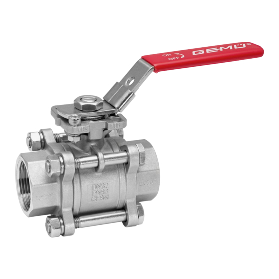
3.5 Funktion tungsplan geführt und hat alle dem Ventil zugeordneten Infor- mationen wie Werkszeugnisse, Prüfdokumentationen und Der 2/2-Wege-Kugelhahn GEMÜ B22 ist aus Metall und mit ei- Wartungshistorien direkt verfügbar. Mit dem CONEXO Portal nem kunststoffbeschichteten Handhebel sowie mit als zentrales Element lassen sich sämtliche Daten sammeln, Topflansch in Edelstahlausführung ausgestattet. -
Page 7: Bestimmungsgemäße Verwendung
Medien gelten die Einsatzbedingungen gemäß der Techni- schen Daten. Für die Steuerung des Produktes kann ein manueller, pneuma- tischer oder elektrischer Antrieb gemäß der Technischen Da- ten verwendet werden. Das Produkt ist bestimmungsgemäß nicht für den Einsatz in explosionsgefährdeten Bereichen geeignet. -
Page 8: Bestelldaten
3 Gehäuseform/Kugelform Zweiwege-Durchgangskörper 4 Anschlussart Gewindemuffe DIN ISO 228 5 Werkstoff Kugelhahn 1.4408 / CF8M (Körper, Anschluss), 1.4401 / SS316 (Kugel, Welle) 6 Dichtwerkstoff PTFE 7 Steuerfunktion Manuell betätigt, Handhebel, abschließbar 8 Sonderausführung ohne GEMÜ B22 8 / 60 www.gemu-group.com... - Page 9 6 Bestelldaten Bestelloption Code Beschreibung 9 CONEXO integrierter RFID-Chip zur elektronischen Identifizierung und Rückver- folgbarkeit www.gemu-group.com 9 / 60 GEMÜ B22...
-
Page 10: Technische Daten
Leckrate nach ANSI FCI70 – B16.104 Leckrate nach EN12266, 6 bar Luft, Leckrate A Kv-Werte: Kv-Werte 1/4" 3/8" 1/2" 17,0 3/4" 34,0 1" 60,0 1¼" 94,0 1½" 213,0 2" 366,0 2½" 595,0 3" 935,0 4" 1700,0 Kv-Werte in m³/h GEMÜ B22 10 / 60 www.gemu-group.com... - Page 11 0,425 1,445 5,95 11,9 23,8 40,8 59,5 90,1 136,0 185,3 3" 0,595 2,975 15,3 29,75 51,0 76,5 114,8 174,3 263,5 4" 0,85 2,975 13,6 34,0 63,75 106,3 161,5 250,8 375,7 569,5 Kv-Werte in m³/h www.gemu-group.com 11 / 60 GEMÜ B22...
-
Page 12: Produktkonformitäten
Gas: Zone 1, 2 IIB Staub: Zone 21, 22 IIIC Innen Bis DN 65 Gas: Zone 0, 1, 2 IIC Staub: keine Zone DN 80 und 100 Gas: Zone 0, 1, 2 IIB Staub: keine Zone GEMÜ B22 12 / 60 www.gemu-group.com... -
Page 13: Mechanische Daten
DN 8 - 20 AB22 20D 0,122 DN 25 - 32 AB22 32D 0,165 DN 40 - 50 AB22 50D 0,398 DN 65 AB22 65D 0,78 DN 80 - 100 AB22 80D 0,78 Gewichte in kg www.gemu-group.com 13 / 60 GEMÜ B22... -
Page 14: Abmessungen
3/4“ 36,0 42,0 1“ 42,0 50,0 11,0 1¼“ 42,0 50,0 11,0 1½“ 50,0 70,0 14,0 2“ 50,0 70,0 14,0 2½“ 50,0 70,0 17,0 3“ 70,0 102,0 17,0 4“ 102,0 125,0 17,0 Maße in mm GEMÜ B22 14 / 60 www.gemu-group.com... - Page 15 81,0 104,5 27,0 80,0 200,0 18,0 160,0 8 x 18,0 160,0 161,0 108,0 310,0 96,0 107,0 10,0 100,0 220,0 18,0 180,0 8 x 18,0 175,0 177,0 123,0 350,0 124,0 113,0 10,0 Maße in mm www.gemu-group.com 15 / 60 GEMÜ B22...
- Page 16 130,0 235,0 124,0 90,0 185,0 81,0 28,0 52,0 27,0 3“ 76,0 155,0 320,0 161,0 108,0 205,0 96,0 32,0 54,5 10,0 4“ 100,0 187,0 320,0 177,0 123,0 240,0 124,0 40,0 58,0 10,0 Maße in mm GEMÜ B22 16 / 60 www.gemu-group.com...
- Page 17 190,0 122,5 88,0 248,0 80,0 84,0 27,0 72,9 76,2 17,5 146,0 1,65 177,0 158,5 105,0 267,0 90,0 88,5 10,0 97,4 101,6 17,5 180,0 2,15 177,0 186,0 120,0 318,0 118,0 100,0 10,0 Maße in mm www.gemu-group.com 17 / 60 GEMÜ B22...
- Page 18 221,0 124,0 90,0 185,3 81,0 52,2 27,0 76,0 89,0 18,0 155,0 6,50 277,0 161,0 108,0 205,0 96,0 54,5 10,0 100,0 116,0 18,0 187,0 8,00 277,0 177,0 123,0 240,0 124,0 58,0 10,0 Maße in mm GEMÜ B22 18 / 60 www.gemu-group.com...
- Page 19 15,0 130,0 221,0 124,0 90,0 254,0 81,0 86,5 27,0 76,0 88,9 18,0 155,0 277,0 161,0 108,0 280,2 96,0 92,0 10,0 100,0 114,3 18,0 187,0 277,0 177,0 123,0 317,0 124,0 96,5 10,0 Maße in mm www.gemu-group.com 19 / 60 GEMÜ B22...
-
Page 20: Herstellerangaben
Passendes, funktionsfähiges und sicheres Werkzeug ver- 4. Lösungsmittel, Chemikalien, Säuren, Kraftstoffe u. ä. nicht ● wenden. mit GEMÜ Produkten und deren Ersatzteilen in einem Raum lagern. 1. Eignung des Produkts für den jeweiligen Einsatzfall sicher- stellen. 5. Kugelhähne in Position „offen“ lagern. -
Page 21: Einbau Bei Schweißstutzen
3. Muttern 19 ganz aufdrehen. 4. Unterlegscheiben 20 entnehmen. 5. Schrauben 18 herausziehen. 6. Mittelteil KM herausnehmen. 7. Schweißstutzen S1 rechts und links an Rohrleitung R an- schweißen. 8. Schweißstutzen abkühlen lassen. 9. Kugelhahn wieder zusammen bauen. www.gemu-group.com 21 / 60 GEMÜ B22... -
Page 22: Einbau Bei Gewindeanschluss
8. Schrauben SN mit Muttern M über Kreuz leicht anziehen. 9. Ausrichtung der Rohrleitung prüfen. 10. Muttern M über Kreuz festziehen. Entsprechende Vorschriften für Anschlüsse beachten! 10.5 Nach dem Einbau ● Alle Sicherheits- und Schutzeinrichtungen wieder anbrin- gen bzw. in Funktion setzen. GEMÜ B22 22 / 60 www.gemu-group.com... -
Page 23: Inbetriebnahme
3. Das Produkt in Betrieb nehmen. AS 21b 16 B Komplett geöffneter Kugelhahn: Handhebel 17 liegt mit Endanschlag 21a an Arretierungsan- schlag AS an. Komplett geschlossener Kugelhahn: Handhebel 17 liegt mit Endanschlag 21b an Arretierungsan- schlag AS an. www.gemu-group.com 23 / 60 GEMÜ B22... - Page 24 4. Bei komplett geöffnetem oder komplett geschlossenem Kugelhahn mit arretiertem Handhebel 17 kann die Stellung mit einer geeigneten Schließvorrichtung (z.B. Vorhänge- schloss VS) in der Bohrung B oberhalb der Handhebelarre- tierung 16 im Handhebel 17 gesichert werden. GEMÜ B22 24 / 60 www.gemu-group.com...
-
Page 25: Fehlerbehebung
Einbau Ventilkörper in Rohrleitung prüfen undicht Flanschverschraubung locker / Gewinde Schrauben am Flansch nachziehen / Ge- undicht winde neu abdichten Flanschdichtungen defekt Flanschdichtungen auswechseln Ventilkörper undicht Ventilkörper undicht oder korrodiert Ventilkörper auf Beschädigungen prüfen, ggf. Ventilkörper tauschen www.gemu-group.com 25 / 60 GEMÜ B22... -
Page 26: Inspektion / Wartung
ð Schlitz quer zur Leitungsrichtung: Nehmen Sie im Zweifelsfall vor Inbetriebnahme Kontakt ● Kugelhahn geschlossen. mit GEMÜ auf. ð Schlitz in Leitungsrichtung: 1. Geeignete Schutzausrüstung gemäß den Regelungen des Kugelhahn offen. Anlagenbetreibers berücksichtigen. HINWEIS 2. Anlage bzw. Anlagenteil stilllegen. 3. Gegen Wiedereinschalten sichern. - Page 27 5. Tellerfedern 11 entnehmen. fest anziehen. 6. Edelstahlbuchse 10 entnehmen. 6. Abdeckkappen 30 wieder aufsetzen. 14.1.2 Dichtungen wechseln HINWEIS Nur Original GEMÜ Ersatzteile verwenden! ● Beim Bestellen von Ersatzteilen komplette Bestellnum- ● mer des Kugelhahns angeben. 1. Handhebel demontieren (siehe Kapitel "Handhebel demon- tieren").
- Page 28 16. Dichtung 6 von Spindel 7 abnehmen. 17. Montage der Dichtungen und des Kugelhahns in umge- 11. Kugel in Geschlossen-Position bringen b. kehrter Reihenfolge. 12. Kugel entnehmen c. 13. Spindel 7 vorsichtig ins Gehäuse drücken und entnehmen. GEMÜ B22 28 / 60 www.gemu-group.com...
-
Page 29: Ersatzteile
V-Ring Spindelpackung O-Ring Handhebel komplett AB22 DN... 14.2.2 Ersatzteile für Anschlussart 59 Pos. Benennung Bestellbezeichnung Kugelhahnkörper komplett BB02 Gehäusedichtung Sitz- und Flanschdichtring BB02 DN...SDS D59 5 Kegelförmige Spindeldichtung V-Ring Spindelpackung O-Ring Handhebel komplett AB22 DN... www.gemu-group.com 29 / 60 GEMÜ B22... -
Page 30: Ausbau Aus Rohrleitung
Produkt keine Rücksendeerklärung bei, erfolgt keine Gut- schrift bzw. keine Erledigung der Reparatur, sondern eine kos- tenpflichtige Entsorgung. 1. Das Produkt reinigen. 2. Rücksendeerklärung bei GEMÜ anfordern. 3. Rücksendeerklärung vollständig ausfüllen. 4. Das Produkt mit ausgefüllter Rücksendeerklärung an GEMÜ schicken. -
Page 31: Konformitätserklärung Nach 2014/68/Eu (Druckgeräterichtlinie)
EN 1983, AD 2000 Hinweis für Produkte mit einer Nennweite ≤ DN 25: Die Produkte werden entwickelt und produziert nach GEMÜ eigenen Verfahrensanweisungen und Qualitätsstandards, welche die Forderungen der ISO 9001 und der ISO 14001 erfüllen. Die Produkte dürfen gemäß Artikel 4, Absatz 3 der Druckgeräterichtlinie 2014/68/EU keine CE-Kennzeichnung tragen. - Page 32 Construction ............34 Pressure-relief hole ..........34 Control ball ............35 Description ............35 Function ............... 35 4 GEMÜ CONEXO ............35 5 Correct use ............... 36 6 Order data ..............37 Order codes ............37 Order example ............. 37 7 Technical data ............
-
Page 33: General Information
Symbol Meaning 1.3 Definition of terms Danger of explosion Working medium The medium that flows through the GEMÜ product. Control function Corrosive chemicals! The possible actuation functions of the GEMÜ product. Control medium The medium whose increasing or decreasing pressure causes Hot plant components! the GEMÜ... -
Page 34: Safety Information
13. Maintain the product correctly. 14. Do not carry out any maintenance work and repairs not de- scribed in this document without consulting the manufac- turer first. In cases of uncertainty: 15. Consult the nearest GEMÜ sales office. GEMÜ B22 34 / 60 www.gemu-group.com... -
Page 35: Control Ball
The app actively guides the maintenance techni- cian through the maintenance schedule and directly provides The GEMÜ B22 2/2-way ball valve is made of metal and is him with all the information assigned to the valve, such as... -
Page 36: Correct Use
The product is not intended for use in potentially explosive areas. The product must not be exposed to pressure fluctuations. If the product is to be used with pressure fluctuations, please contact GEMÜ. GEMÜ B22 36 / 60 www.gemu-group.com... -
Page 37: Order Data
1.4408 / CF8M (body, connection), 1.4401 / SS316 (ball, shaft) 6 Seal material PTFE 7 Control function Manually operated, hand lever, lockable 8 Special version Without 9 CONEXO Integrated RFID chip for electronic identification and traceability www.gemu-group.com 37 / 60 GEMÜ B22... -
Page 38: Technical Data
Leakage rate according to EN12266, 6 bar air, leakage rate A Kv values: Kv values 1/4" 3/8" 1/2" 17.0 3/4" 34.0 1" 60.0 1¼" 94.0 1½" 213.0 2" 366.0 2½" 595.0 3" 935.0 4" 1700.0 Kv values in m³/h GEMÜ B22 38 / 60 www.gemu-group.com... - Page 39 0.425 1.445 5.95 11.9 23.8 40.8 59.5 90.1 136.0 185.3 3" 0.595 2.975 15.3 29.75 51.0 76.5 114.8 174.3 263.5 4" 0.85 2.975 13.6 34.0 63.75 106.3 161.5 250.8 375.7 569.5 Kv values in m³/h www.gemu-group.com 39 / 60 GEMÜ B22...
-
Page 40: Product Conformities
Gas: Zone 1, 2 IIB Dust: Zone 21, 22 IIIC Internal Up to DN 65 Gas: Zone 0, 1, 2 IIC Dust: No zone DN 80 and 100 Gas: Zone 0, 1, 2 IIB Dust: No zone GEMÜ B22 40 / 60 www.gemu-group.com... -
Page 41: Mechanical Data
DN 8 - 20 AB22 20D 0.122 DN 25 - 32 AB22 32D 0.165 DN 40 - 50 AB22 50D 0.398 DN 65 AB22 65D 0.78 DN 80 - 100 AB22 80D 0.78 Weights in kg www.gemu-group.com 41 / 60 GEMÜ B22... -
Page 42: Dimensions
3/4“ 36.0 42.0 1“ 42.0 50.0 11.0 1¼“ 42.0 50.0 11.0 1½“ 50.0 70.0 14.0 2“ 50.0 70.0 14.0 2½“ 50.0 70.0 17.0 3“ 70.0 102.0 17.0 4“ 102.0 125.0 17.0 Dimensions in mm GEMÜ B22 42 / 60 www.gemu-group.com... - Page 43 81.0 104.5 27.0 80.0 200.0 18.0 160.0 8 x 18.0 160.0 161.0 108.0 310.0 96.0 107.0 10.0 100.0 220.0 18.0 180.0 8 x 18.0 175.0 177.0 123.0 350.0 124.0 113.0 10.0 Dimensions in mm www.gemu-group.com 43 / 60 GEMÜ B22...
- Page 44 130.0 235.0 124.0 90.0 185.0 81.0 28.0 52.0 27.0 3“ 76.0 155.0 320.0 161.0 108.0 205.0 96.0 32.0 54.5 10.0 4“ 100.0 187.0 320.0 177.0 123.0 240.0 124.0 40.0 58.0 10.0 Dimensions in mm GEMÜ B22 44 / 60 www.gemu-group.com...
- Page 45 190.0 122.5 88.0 248.0 80.0 84.0 27.0 72.9 76.2 17.5 146.0 1.65 177.0 158.5 105.0 267.0 90.0 88.5 10.0 97.4 101.6 17.5 180.0 2.15 177.0 186.0 120.0 318.0 118.0 100.0 10.0 Dimensions in mm www.gemu-group.com 45 / 60 GEMÜ B22...
- Page 46 221.0 124.0 90.0 185.3 81.0 52.2 27.0 76.0 89.0 18.0 155.0 6.50 277.0 161.0 108.0 205.0 96.0 54.5 10.0 100.0 116.0 18.0 187.0 8.00 277.0 177.0 123.0 240.0 124.0 58.0 10.0 Dimensions in mm GEMÜ B22 46 / 60 www.gemu-group.com...
- Page 47 15.0 130.0 221.0 124.0 90.0 254.0 81.0 86.5 27.0 76.0 88.9 18.0 155.0 277.0 161.0 108.0 280.2 96.0 92.0 10.0 100.0 114.3 18.0 187.0 277.0 177.0 123.0 317.0 124.0 96.5 10.0 Dimensions in mm www.gemu-group.com 47 / 60 GEMÜ B22...
-
Page 48: Manufacturer's Information
Use appropriate, functional and safe tools. 4. Do not store solvents, chemicals, acids, fuels or similar ● fluids in the same room as GEMÜ products and their spare 1. Ensure the product is suitable for the relevant application. parts. 2. Check the technical data of the product and the materials. -
Page 49: Installation With Butt Weld Spigots
5. Pull out the bolts 18. 6. Remove the centre section KM. 7. Weld butt weld spigots S1 right and left to the piping R. 8. Allow the butt weld spigots to cool down. 9. Reassemble the ball valve. www.gemu-group.com 49 / 60 GEMÜ B22... -
Page 50: Installation With Threaded Connections
8. Slightly tighten the bolts SN and nuts M diagonally. 9. Check the alignment of the piping. 10. Tighten nuts M diagonally. Comply with appropriate regulations for the connections! 10.5 After the installation ● Re-attach or reactivate all safety and protective devices. GEMÜ B22 50 / 60 www.gemu-group.com... -
Page 51: Commissioning
The hand lever 17 is located at the travel stop 21a on the lock- ing stop AS. Ball valve fully closed: The hand lever 17 is located at the travel stop 21b on the lock- ing stop AS. www.gemu-group.com 51 / 60 GEMÜ B22... - Page 52 4. If the ball valve is fully open or fully closed with the hand lever locked in place 17, the position can be secured on the hand lever 17 using an appropriate lock (e.g. padlock VS) in the bolt hole B above the hand lever locking device GEMÜ B22 52 / 60 www.gemu-group.com...
-
Page 53: Troubleshooting
Flange bolting loose/thread leaking Retighten flange bolting / reseal threads Flange seals faulty Replace flange seals Valve body leaks Valve body leaks or is corroded Check valve body for damage, replace valve body if necessary www.gemu-group.com 53 / 60 GEMÜ B22... -
Page 54: Inspection/Maintenance
Servicing and maintenance work must only be performed ● by trained personnel. Do not extend hand lever. GEMÜ shall assume no liability 1. Check the position of the ball indicated by the groove SZ ● whatsoever for damages caused by improper handling or and compare with position indicator, rotate ball valve to third-party actions. - Page 55 6. Remove stainless steel sleeve 10. 6. Put the protective caps 30 back on. 14.1.2 Replacing the seals NOTICE Only use genuine GEMÜ spare parts. ● When ordering spare parts, specify the complete order ● number of the ball valve.
- Page 56 16. Remove seal 6 from spindle 7. 17. Mount the seals and the ball valve in reverse order. 11. Move the ball to the closed position b. 12. Remove ball c. 13. Carefully press spindle 7 into housing and remove. GEMÜ B22 56 / 60 www.gemu-group.com...
-
Page 57: Spare Parts
14.2.2 Spare parts for connection type 59 Item Name Order description Ball valve body assembly complete BB02 Housing seal Seat and flange seal BB02 DN...SDS D59 5 Conical spindle seal V-ring spindle packing O-ring Hand lever complete AB22 DN... www.gemu-group.com 57 / 60 GEMÜ B22... -
Page 58: Removal From Piping
Returned goods can be processed only when this note is completed. If no return delivery note is included with the product, GEMÜ cannot process credits or repair work but will dispose of the goods at the operator's expense. -
Page 59: Declaration Of Conformity According To 2014/68/Eu (Pressure Equipment Directive)
EN 1983, AD 2000 Note for products with a nominal size ≤ DN 25: The products are developed and produced according to GEMÜ process instructions and quality standards which comply with the requirements of ISO 9001 and ISO 14001. According to Article 4, Paragraph 3 of the Pressure Equipment Directive 2014/68/EU these products must not be identified by a CE-label. - Page 60 GEMÜ Gebr. Müller Apparatebau GmbH & Co. KG Subject to alteration *88715743* Fritz-Müller-Straße 6–8, 74653 Ingelfingen-Criesbach, Germany 01.2021 | 88715743 Phone +49 (0) 7940 1230 · info@gemue.de www.gemu-group.com...
Need help?
Do you have a question about the B22 and is the answer not in the manual?
Questions and answers