
Related Manuals for GEM B24


Summary of Contents for GEM B24
- Page 1 GEMÜ B24 Manuell betätigter Kugelhahn Manually operated ball valve Betriebsanleitung Operating instructions Weitere Informationen Webcode: GW-B24...
- Page 2 Alle Rechte wie Urheberrechte oder gewerbliche Schutzrechte werden ausdrücklich vorbehalten. All rights including copyrights or industrial property rights are expressly reserved. Dokument zum künftigen Nachschlagen aufbewahren. Keep the document for future reference. © GEMÜ Gebr. Müller Apparatebau GmbH & Co. KG 27.11.2020 GEMÜ B24 2 / 52...
-
Page 3: Table Of Contents
Verwendete Symbole .......... Begriffsbestimmungen ........Warnhinweise ............2 Sicherheitshinweise ..........3 Produktbeschreibung ..........Aufbau ..............Beschreibung ............Funktion ............... 4 GEMÜ CONEXO ............5 Bestimmungsgemäße Verwendung ......6 Bestelldaten .............. Bestellcodes ............Bestellbeispiel ............. 7 Technische Daten ............. Medium ..............Temperatur ............ -
Page 4: Allgemeines
Auszuführende Tätigkeiten Aggressive Chemikalien! Reaktion(en) auf Tätigkeiten – Aufzählungen 1.3 Begriffsbestimmungen Heiße Anlagenteile! Betriebsmedium Medium, das durch das GEMÜ Produkt fließt. 1.4 Warnhinweise Warnhinweise sind, soweit möglich, nach folgendem Schema gegliedert: SIGNALWORT Art und Quelle der Gefahr Mögliches gefahren- Mögliche Folgen bei Nichtbeachtung. -
Page 5: Sicherheitshinweise
2. Schrauben und Kunststoffteile am Produkt nicht lackieren. 3.2 Beschreibung 3. Installation und Inbetriebnahme durch eingewiesenes Fachpersonal durchführen. Der dreiteilige 2/2-Wege Metall-Kugelhahn GEMÜ B24 wird manuell betätigt. Die beim Kugelhahnkörper eingesetzte Edel- 4. Montage- und Betriebspersonal ausreichend schulen. stahllegierung 1.4435 (Materialzusammensetzung entspricht 5. -
Page 6: Gemü Conexo
Das Produkt ist für den Einbau in Rohrleitungen und zur Steue- verwalten und weiterverarbeiten. rung eines Betriebsmediums konzipiert. 1. Das Produkt gemäß den technischen Daten einsetzen. Weitere Informationen zu GEMÜ CONEXO finden Sie auf: 2. Beiblatt nach ATEX beachten. www.gemu-group.com/conexo Anbringung des RFID-Chips Dieses Produkt besitzt in entsprechender Ausführung mit CO-... -
Page 7: Bestelldaten
1.4435 / ASTM A351, low Ferrit <3% (gleichwertig 316L Δ Fe<3%) (Körper, Anschluss, Kugel), 1.4409 / SS316L (Spindel) 6 Dichtwerkstoff TFM 1600 (FDA-Zertifizierung) 7 Steuerfunktion Manuell betätigt, Handhebel, abschließbar 8 Sonderausführung ohne 9 CONEXO ohne www.gemu-group.com 7 / 52 GEMÜ B24... -
Page 8: Technische Daten
Code 17: Stutzen EN 10357 Serie A (ehemals DIN 11850 Reihe 2) / DIN 11866 Reihe A Code 59: Stutzen ASME BPE Code 60: Stutzen ISO 1127 / EN 10357 Serie C / DIN 11866 Reihe B Code 80: Clamp ASME BPE, Baulänge FTF ASME BPE GEMÜ B24 8 / 52 www.gemu-group.com... -
Page 9: Produktkonformitäten
II -/2D Ex h -/IIIC T180 °C -/Db X DN 80 und 100 Gas: II 2G Ex h IIB T6 … T2 Gb X Staub: II -/2D Ex h -/IIIC T180 °C -/Db X www.gemu-group.com 9 / 52 GEMÜ B24... -
Page 10: Mechanische Daten
DN 8 - 20 AB24 20D 0,122 DN 25 - 32 AB24 32D 0,165 DN 40 - 50 AB24 50D 0,398 DN 65 - 80 AB24 80D 0,78 DN 100 AB24100D 0,96 Gewichte in kg GEMÜ B24 10 / 52 www.gemu-group.com... -
Page 11: Abmessungen
50,0 11,0 13,0 1½“ 50,0 70,0 14,0 15,0 2“ 50,0 70,0 14,0 16,0 2½“ 50,0 70,0 17,0 18,0 10,5 3“ 70,0 102,0 17,0 18,0 10,5 4“ 102,0 125,0 17,0 18,0 10,5 Maße in mm www.gemu-group.com 11 / 52 GEMÜ B24... - Page 12 4 x M14 32,0 140,0 300,0 81,0 85,0 158,0 280,0 96,0 92,0 102,0 4 x M16 32,0 150,0 300,0 100,0 104,0 198,5 308,0 122,0 93,0 132,0 6 x M20 38,0 195,0 350,0 Maße in mm GEMÜ B24 12 / 52 www.gemu-group.com...
- Page 13 4 x M14 143,0 300,0 32,0 72,9 76,2 1,65 150,0 276,9 91,7 92,6 98,0 4 x M16 154,0 300,0 32,0 97,4 101,6 187,5 304,9 118,3 93,3 130,0 6 x M16 197,0 350,0 38,0 Maße in mm www.gemu-group.com 13 / 52 GEMÜ B24...
- Page 14 4 x M14 140,0 300,0 32,0 84,3 88,9 158,0 280,0 96,0 92,0 102,0 4 x M16 150,0 300,0 32,0 109,7 114,3 198,5 308,0 122,0 93,0 132,0 6 x M20 195,0 350,0 38,0 Maße in mm GEMÜ B24 14 / 52 www.gemu-group.com...
- Page 15 4 x M14 143,0 300,0 32,0 72,9 90,9 1,65 150,0 196,3 91,7 52,3 98,0 4 x M16 154,0 300,0 32,0 97,4 118,9 187,5 241,3 118,3 61,5 130,0 6 x M16 197,0 350,0 38,0 Maße in mm www.gemu-group.com 15 / 52 GEMÜ B24...
-
Page 16: Herstellerangaben
Passendes, funktionsfähiges und sicheres Werkzeug ver- 4. Lösungsmittel, Chemikalien, Säuren, Kraftstoffe u. ä. nicht ● wenden. mit GEMÜ Produkten und deren Ersatzteilen in einem Raum lagern. 1. Eignung des Produkts für den jeweiligen Einsatzfall sicher- stellen. 5. Kugelhähne in Position „offen“ lagern. -
Page 17: Einbau Bei Schweißstutzen
9. Muttern über Kreuz anziehen, mit Schraubenschlüssel ge- genhalten. 2. Rohrleitungen 1 und 4 links und rechts an den Schweiß- stutzen 2 und 3 ausrichten und anheften. Nennweite Anzugsmoment DN10 DN15 DN20 DN25 DN32 DN40 DN50 DN65 DN80 DN100 www.gemu-group.com 17 / 52 GEMÜ B24... -
Page 18: Einbau Bei Clampanschluss
4. Clamp des Kugelhahns und Clamp der Rohrleitung mit passender Verschlussklemme 4 verbinden. 5. Nur Verbindungselemente aus zulässigen Werkstoffen verwenden! 10.4 Nach dem Einbau ● Alle Sicherheits- und Schutzeinrichtungen wieder anbrin- gen bzw. in Funktion setzen. GEMÜ B24 18 / 52 www.gemu-group.com... -
Page 19: Betrieb
Handhebel 17 liegt mit Endanschlag 21a an Arretierungsan- schlag AS an. Komplett geschlossener Kugelhahn: Handhebel 17 liegt mit Endanschlag 21b an Arretierungsan- schlag AS an. HINWEIS ▶ Der Öffnungsgrad ist stufenlos wählbar, jedoch sind diese Zwischenstufen nicht arretierbar und nicht abschließbar. www.gemu-group.com 19 / 52 GEMÜ B24... -
Page 20: Fehlerbehebung
Verschlussklemme nachziehen undicht locker Bei Clampanschluss: Dichtung defekt Dichtung austauschen Unsachgemäßer Einbau Einbau Ventilkörper in Rohrleitung prüfen Ventilkörper undicht Ventilkörper undicht oder korrodiert Ventilkörper auf Beschädigungen prüfen, ggf. Ventilkörper tauschen Schrauben des Kugelhahnkörpers locker Schrauben nachziehen GEMÜ B24 20 / 52 www.gemu-group.com... -
Page 21: Inspektion / Wartung
übernimmt GEMÜ keinerlei Haftung. Nehmen Sie im Zweifelsfall vor Inbetriebnahme Kontakt ● mit GEMÜ auf. 1. Geeignete Schutzausrüstung gemäß den Regelungen des Anlagenbetreibers berücksichtigen. 2. Anlage bzw. Anlagenteil stilllegen. 3. Gegen Wiedereinschalten sichern. 4. Anlage bzw. Anlagenteil drucklos schalten. -
Page 22: Ersatzteile
Flanschdichtung (2x) Dichtscheibe Spindel BB04 SDS O-Ring V-Ring Spindelpackung Antrieb AB24 14.1.2 Ersatzteile für Anschlussarten 59, 80 Pos. Benennung Bestellbezeichnung Kugelhahnkörper Sitzdichtring (2x) Flanschdichtung (2x) Dichtscheibe Spindel BB04 SDS O-Ring V-Ring Spindelpackung Antrieb AB24 GEMÜ B24 22 / 52 www.gemu-group.com... -
Page 23: Austausch Von Ersatzteilen
14. Lasche der Sicherungsscheibe 7 nach oben biegen. 15. Spindel so drehen, dass Kugelmitnehmer längs zur Rohr- leitungsrichtung steht und Kugel 15 mit leichter Drehbewe- gung auf Kugelmitnehmer schieben. 16. Sitzdichtringe 4 und Flanschdichtringe 5 von beiden Seiten einlegen. www.gemu-group.com 23 / 52 GEMÜ B24... -
Page 24: 17 Rücksendung
Produkt keine Rücksendeerklärung bei, erfolgt keine Gut- schrift bzw. keine Erledigung der Reparatur, sondern eine kos- tenpflichtige Entsorgung. 1. Das Produkt reinigen. 2. Rücksendeerklärung bei GEMÜ anfordern. 3. Rücksendeerklärung vollständig ausfüllen. 4. Das Produkt mit ausgefüllter Rücksendeerklärung an GEMÜ schicken. -
Page 25: Konformitätserklärung Nach 2014/68/Eu (Druckgeräterichtlinie)
EN 1983, AD 2000 Hinweis für Produkte mit einer Nennweite ≤ DN 25: Die Produkte werden entwickelt und produziert nach GEMÜ eigenen Verfahrensanweisungen und Qualitätsstandards, welche die Forderungen der ISO 9001 und der ISO 14001 erfüllen. Die Produkte dürfen gemäß Artikel 4, Absatz 3 der Druckgeräterichtlinie 2014/68/EU keine CE-Kennzeichnung tragen. - Page 26 2 Safety information ............ 28 3 Product description ........... 28 Construction ............28 Description ............28 Function ............... 28 4 GEMÜ CONEXO ............29 5 Correct use ............... 29 6 Order data ..............30 Order codes ............30 Order example ............. 30 7 Technical data ............
-
Page 27: General Information
– Lists 1.3 Definition of terms Hot plant components! Working medium The medium that flows through the GEMÜ product. 1.4 Warning notes Wherever possible, warning notes are organised according to the following scheme: SIGNAL WORD Type and source of the danger... -
Page 28: Safety Information
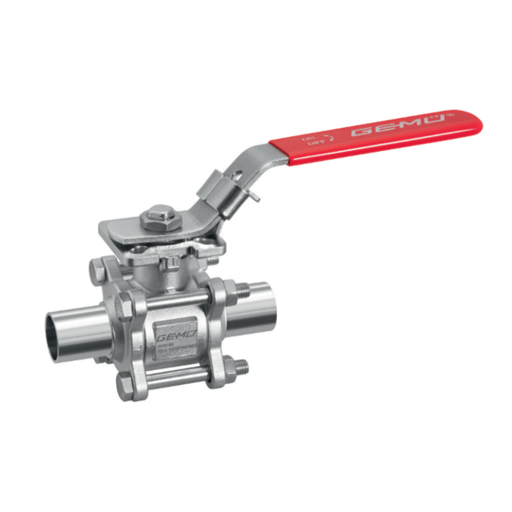
3.2 Description 4. Provide adequate training for installation and operating The GEMÜ B24 3-piece 2/2-way metal ball valve is manually personnel. operated. The 1.4435 stainless steel alloy material composi- 5. Ensure that the contents of the document have been fully tion used for the ball valve body (compliant with 316L) with a understood by the responsible personnel. -
Page 29: Gemü Conexo
1. Use the product in accordance with the technical data. collect, manage and process all data. 2. Note the supplement acc. to ATEX For further information on GEMÜ CONEXO please visit: www.gemu-group.com/conexo Installing the RFID chip In the corresponding design with CONEXO, this product has an RFID chip (1) for electronic recognition. -
Page 30: Order Data
1.4435 / ASTM A351, low ferrite <3% (equivalent to 316L Δ Fe<3%) (body, connection, ball), 1.4409 / SS316L (spindle) 6 Seal material TFM 1600 (FDA certification) 7 Control function Manually operated, hand lever, lockable 8 Special version Without 9 CONEXO without GEMÜ B24 30 / 52 www.gemu-group.com... -
Page 31: Technical Data
Code 17: Spigot EN 10357 series A (formerly DIN 11850 series 2)/DIN 11866 series A Code 59: Spigot ASME BPE Code 60: Spigot ISO 1127/EN 10357 series C/DIN 11866 series B Code 80: Clamp ASME BPE, face-to-face dimension FTF ASME BPE www.gemu-group.com 31 / 52 GEMÜ B24... -
Page 32: Product Conformities
II -/2D Ex h -/IIIC T180 °C -/Db X DN 80 and 100 Gas: II 2G Ex h IIB T6 … T2 Gb X Dust: II -/2D Ex h -/IIIC T180 °C -/Db X GEMÜ B24 32 / 52 www.gemu-group.com... -
Page 33: Mechanical Data
DN 8 - 20 AB24 20D 0.122 DN 25 - 32 AB24 32D 0.165 DN 40 - 50 AB24 50D 0.398 DN 65 - 80 AB24 80D 0.78 DN 100 AB24100D 0.96 Weights in kg Ball valve www.gemu-group.com 33 / 52 GEMÜ B24... -
Page 34: Dimensions
42.0 50.0 11.0 13.0 1½“ 50.0 70.0 14.0 15.0 2“ 50.0 70.0 14.0 16.0 2½“ 50.0 70.0 17.0 18.0 3“ 70.0 102.0 17.0 18.0 10.5 4“ 102.0 125.0 17.0 18.0 10.5 Dimensions in mm GEMÜ B24 34 / 52 www.gemu-group.com... - Page 35 4 x M14 32.0 140.0 300.0 81.0 85.0 158.0 280.0 96.0 92.0 102.0 4 x M16 32.0 150.0 300.0 100.0 104.0 198.5 308.0 122.0 93.0 132.0 6 x M20 38.0 195.0 350.0 Dimensions in mm www.gemu-group.com 35 / 52 GEMÜ B24...
- Page 36 4 x M14 143.0 300.0 32.0 72.9 76.2 1.65 150.0 276.9 91.7 92.6 98.0 4 x M16 154.0 300.0 32.0 97.4 101.6 187.5 304.9 118.3 93.3 130.0 6 x M16 197.0 350.0 38.0 Dimensions in mm GEMÜ B24 36 / 52 www.gemu-group.com...
- Page 37 4 x M14 140.0 300.0 32.0 84.3 88.9 158.0 280.0 96.0 92.0 102.0 4 x M16 150.0 300.0 32.0 109.7 114.3 198.5 308.0 122.0 93.0 132.0 6 x M20 195.0 350.0 38.0 Dimensions in mm www.gemu-group.com 37 / 52 GEMÜ B24...
- Page 38 4 x M14 143.0 300.0 32.0 72.9 90.9 1.65 150.0 196.3 91.7 52.3 98.0 4 x M16 154.0 300.0 32.0 97.4 118.9 187.5 241.3 118.3 61.5 130.0 6 x M16 197.0 350.0 38.0 Dimensions in mm GEMÜ B24 38 / 52 www.gemu-group.com...
-
Page 39: Manufacturer's Information
Use appropriate, functional and safe tools. 4. Do not store solvents, chemicals, acids, fuels or similar ● fluids in the same room as GEMÜ products and their spare 1. Ensure the product is suitable for the relevant application. parts. 2. Check the technical data of the product and the materials. -
Page 40: Installation With Butt Weld Spigots
2. Align the pipes 1 and 4 on the left and right with the butt weld spigots 2 and 3, and attach them to the spigots. Nominal size Torque DN10 DN15 DN20 DN25 DN32 DN40 DN50 DN65 DN80 DN100 GEMÜ B24 40 / 52 www.gemu-group.com... -
Page 41: Installation With Clamp Connections
4. Connect the clamp of the ball valve and the clamp of the piping with the appropriate sealing clamp 4. 5. Only use connector elements made of approved materials! 10.4 After the installation ● Re-attach or reactivate all safety and protective devices. www.gemu-group.com 41 / 52 GEMÜ B24... -
Page 42: Operation
Ball valve fully closed: The hand lever 17 is located at the travel stop 21b on the lock- ing stop AS. NOTICE ▶ While the valve opening is continuously selectable, these intermediate positions are not lockable. GEMÜ B24 42 / 52 www.gemu-group.com... -
Page 43: Troubleshooting
Check installation of valve body in piping Valve body leaks Valve body leaks or is corroded Check valve body for damage, replace valve body if necessary Bolts of the ball valve body are loose Retighten bolts www.gemu-group.com 43 / 52 GEMÜ B24... -
Page 44: Inspection/Maintenance
CAUTION Servicing and maintenance work must only be performed ● by trained personnel. Do not extend hand lever. GEMÜ shall assume no liability ● whatsoever for damages caused by improper handling or third-party actions. In case of doubt, contact GEMÜ prior to commissioning. -
Page 45: Spare Parts
14.1.2 Spare parts for connection types 59, 80 Item Name Order designation Ball valve body Seat seal (2 x) Flange seal (2 x) Sealing washer spindle BB04 SDS O-ring V-ring spindle packing Actuator AB24 www.gemu-group.com 45 / 52 GEMÜ B24... -
Page 46: Replacement Of Spare Parts
15. Turn the spindle so that the ball actuator runs alongside the direction of piping, and push the ball 15 onto the ball actuator with a slight rotating movement. 16. Insert the seat seals 4 and flange seals 5 from both sides. GEMÜ B24 46 / 52 www.gemu-group.com... -
Page 47: Returns
Returned goods can be processed only when this note is completed. If no return delivery note is included with the product, GEMÜ cannot process credits or repair work but will dispose of the goods at the operator's expense. -
Page 48: Declaration Of Conformity According To 2014/68/Eu (Pressure Equipment Directive)
EN 1983, AD 2000 Note for products with a nominal size ≤ DN 25: The products are developed and produced according to GEMÜ process instructions and quality standards which comply with the requirements of ISO 9001 and ISO 14001. According to Article 4, Paragraph 3 of the Pressure Equipment Directive 2014/68/EU these products must not be identified by a CE-label. - Page 49 GEMÜ B24 49 / 52 www.gemu-group.com...
- Page 50 GEMÜ B24 50 / 52 www.gemu-group.com...
- Page 51 51 / 52 GEMÜ B24...
- Page 52 GEMÜ Gebr. Müller Apparatebau GmbH & Co. KG Subject to alteration *88714668* Fritz-Müller-Straße 6–8, 74653 Ingelfingen-Criesbach, Germany 11.2020 | 88714668 Phone +49 (0) 7940 1230 · info@gemue.de www.gemu-group.com...
Need help?
Do you have a question about the B24 and is the answer not in the manual?
Questions and answers