
Subscribe to Our Youtube Channel
Related Manuals for GEM B44


Summary of Contents for GEM B44
- Page 1 GEMÜ B44 Pneumatically operated ball valve Operating instructions further information webcode: GW-B44...
- Page 2 All rights including copyrights or industrial property rights are expressly reserved. Keep the document for future reference. © GEMÜ Gebr. Müller Apparatebau GmbH & Co. KG 08.06.2021 GEMÜ B44 2 / 34 www.gemu-group.com...
-
Page 3: Table Of Contents
Definition of terms ..........Warning notes ............. 2 Safety information ............ 3 Product description ........... Construction ............Description ............Function ............... 4 GEMÜ CONEXO ............5 Correct use ............... 6 Order data ..............7 Technical data ............Medium ..............Temperature ............Pressure ............... -
Page 4: General Information
– Lists 1.3 Definition of terms Hot plant components! Working medium The medium that flows through the GEMÜ product. 1.4 Warning notes Do not open the actuator! Wherever possible, warning notes are organised according to the following scheme: SIGNAL WORD... -
Page 5: Safety Information
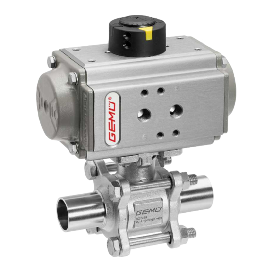
2. Do not paint the bolts and plastic parts of the product. 3. Carry out installation and commissioning using trained 3.2 Description personnel. The GEMÜ B44 3-piece 2/2-way metal ball valve is pneumatic- 4. Provide adequate training for installation and operating ally operated. The 1.4435 stainless steel alloy material com- personnel. -
Page 6: Gemü Conexo
The product GEMÜ B44 is intended for use in potentially ex- plosive areas of zones 1 and 2 with gases, mists or vapours Thanks to serialization, every valve and every relevant valve... -
Page 7: Order Data
DN 20 Actuator, pneumatic, double acting, clockwise rota- BU30AD DN 25 tion, DN 32 ADA0300U F07/10 S22 DN 40 Actuator GEMÜ ASR DN 50 Actuator, pneumatic, single acting, clockwise rota- AU02FA DN 65 tion, spring closing, ASR0020US08F04 S14S11 DN 80... - Page 8 DU22AD Actuator, pneumatic, single acting, clockwise rota- SU45KG tion, tion, spring closing, DR0220U F07/10 S22 SC0450U 6F10/12 S27 Actuator GEMÜ SC 9 Actuator particulars Code Actuator, pneumatic, single acting, clockwise rota- SU03KO Gen. industrial version, tion, spring closing, body alu, anodising layer 25-35µm, end caps alu,...
-
Page 9: Technical Data
Leakage rate: Leakage rate according to ANSI FCI70 – B16.104 Leakage rate according to EN12266, 6 bar air, leakage rate A www.gemu-group.com 9 / 34 GEMÜ B44... -
Page 10: Product Conformities
Code 60: Spigot ISO 1127/EN 10357 series C/DIN 11866 series B Code 80: Clamp ASME BPE, face-to-face dimension FTF ASME BPE 7.4 Product conformities Machinery Directive: 2006/42/EC Pressure Equipment Dir- 2014/68/EU ective: Food: Regulation (EC) No. 1935/2004 Regulation (EC) No. 10/2011 GEMÜ B44 10 / 34 www.gemu-group.com... -
Page 11: Mechanical Data
It can be found in the product-specific ATEX documentation and the ATEX type plate. 7.5 Mechanical data 90° travel: GEMÜ ADA /ASR: ±5° adjustable (85° - 95°) GEMÜ DR /SC: 20° adjustable (75° - 95°) Torques: Seal material (code 1/4"... - Page 12 0200U 0300U 10.8 0500U 11.2 15.4 0850U 16.9 22.2 Weights in kg Actuator type DR/SC Type double act- single acting 0015U 0030U 0060U 0100U 0150U 0220U 0300U 12.0 0450U 14.0 17.0 Weights in kg GEMÜ B44 12 / 34 www.gemu-group.com...
-
Page 13: Dimensions
M8 x 16.0 102.0 M10 x 16.0 0500U 22.0 28.5 32.0 39.0 102.0 M10 x 16.0 0850U F10 / F12 27.0 36.5 39.0 49.0 102.0 M10 x 17.0 125.0 M12 x 20.0 Dimensions in mm www.gemu-group.com 13 / 34 GEMÜ B44... - Page 14 30.0 0200U 165.0 135.0 135.5 78.0 G1/4" 225.0 299.0 40.0 30.0 0500U 199.0 169.0 173.0 96.0 G1/4" 304.0 397.0 40.0 30.0 0850U 221.0 191.0 191.5 106.0 G1/4" 372.0 473.0 40.0 30.0 Dimensions in mm GEMÜ B44 14 / 34 www.gemu-group.com...
- Page 15 F05/F07 17.0 23.4 18.5 25.5 50.0 70.0 0150U F07/F10 22.0 25.0 70.0 102.0 0220U F07/F10 22.0 24.0 70.0 102.0 0300U F07/F10 22.0 35.0 70.0 102.0 0450U F10/F12 27.0 29.0 70.0 102.0 Dimensions in mm www.gemu-group.com 15 / 34 GEMÜ B44...
- Page 16 145.0 136.0 72.0 58.0 80.0 G1/4" 30.0 304.0 27.0 0300U 187.0 157.0 146.5 77.0 58.0 80.0 G1/4" 30.0 333.0 27.0 0450U 207.0 177.0 166.0 86.0 67.5 80.0 G1/4" 30.0 394.5 27.0 Dimensions in mm GEMÜ B44 16 / 34 www.gemu-group.com...
- Page 17 4 x M14 66.0 70.0 131.5 254.0 82.0 86.0 92.0 4 x M14 81.0 85.0 158.0 280.0 96.0 92.0 102.0 4 x M16 100.0 104.0 198.5 308.0 122.0 93.0 132.0 6 x M20 Dimensions in mm www.gemu-group.com 17 / 34 GEMÜ B44...
- Page 18 63.5 1.65 126.0 254.1 77.1 88.5 89.0 4 x M14 72.9 76.2 1.65 150.0 276.9 91.7 92.6 98.0 4 x M16 97.4 101.6 187.5 304.9 118.3 93.3 130.0 6 x M16 Dimensions in mm GEMÜ B44 18 / 34 www.gemu-group.com...
- Page 19 4 x M14 72.1 76.1 131.5 254.0 82.0 86.0 92.0 4 x M14 84.3 88.9 158.0 280.0 96.0 92.0 102.0 4 x M16 109.7 114.3 198.5 308.0 122.0 93.0 132.0 6 x M20 Dimensions in mm www.gemu-group.com 19 / 34 GEMÜ B44...
- Page 20 77.4 1.65 126.0 171.5 77.1 47.2 89.0 4 x M14 72.9 90.9 1.65 150.0 196.3 91.7 52.3 98.0 4 x M16 97.4 118.9 187.5 241.3 118.3 61.5 130.0 6 x M16 Dimensions in mm GEMÜ B44 20 / 34 www.gemu-group.com...
-
Page 21: Manufacturer's Information
Provide precautionary measures against exceeding the ● 4. Do not store solvents, chemicals, acids, fuels or similar maximum permitted pressures caused by pressure fluids in the same room as GEMÜ products and their spare surges (water hammer). parts. CAUTION 5. Store the ball valves in the "open" position. -
Page 22: Installation With Butt Weld Spigots
13. Only install the product between matching aligned pipes (see chapters below). 14. Installation position: preferably actuator upwards. 15. Direction of the working medium: optional. 2. Centre and fix butt weld spigots S right and left on piping GEMÜ B44 22 / 34 www.gemu-group.com... -
Page 23: Installation With Clamp Connections
2. Carefully align the ball valve body 1 centrally between the pipes with clamps (C1 and C2). 3. Centre the seals D accurately. Seals are not included in the scope of delivery. 9. Tighten nuts 19a - 19d diagonally, holding them with a wrench. www.gemu-group.com 23 / 34 GEMÜ B44... -
Page 24: After The Installation
● Re-attach or reactivate all safety and protective devices. 2 (NO), U (NO) 3 (DA), T (DA) + = available / - = not available (for connectors 2 / 4 see picture in chapter "Connecting the control medium") GEMÜ B44 24 / 34 www.gemu-group.com... -
Page 25: Optical Position Indicator
Double acting (DA) 2: Control medium (open) 14 Operation 4: Control medium (close) Operate the product according to the control function (see For connectors 2 / 4 see picture above also chapter "Pneumatic connection"). www.gemu-group.com 25 / 34 GEMÜ B44... -
Page 26: Troubleshooting
For clamp connections: Gasket faulty Replace gasket Incorrect installation Check installation of valve body in piping Valve body leaks Incorrect installation Check installation of valve body in piping Bolts of the ball valve body are loose Retighten bolts GEMÜ B44 26 / 34 www.gemu-group.com... -
Page 27: Inspection/Maintenance
Servicing and maintenance work must only be performed ● by trained personnel. Do not extend hand lever. GEMÜ shall assume no liability 1. Check the position of the ball indicated by the groove SZ ● whatsoever for damages caused by improper handling or and compare with position indicator, rotate ball valve to third-party actions. -
Page 28: Spare Parts
Seat seal (2 x) Flange seal (2 x) Sealing washer spindle BB04 SDS O-ring V-ring spindle packing Actuator ADA/ASR, DR/SC Pneumatic actuator, double acting Pneumatic actuator, single acting Pneumatic actuator, double acting Pneumatic actuator, single acting GEMÜ B44 28 / 34 www.gemu-group.com... -
Page 29: Disassembly Of Actuator From Ball Valve Body
Check parts for 4. Do not lose the washers 4. potential damage; replace if necessary (only use genuine parts from GEMÜ). 5. Remove the actuator 2 from the ball valve body 3. www.gemu-group.com 29 / 34... -
Page 30: Assembling The Spare Parts
DN100 washers and tighten the nuts 14 evenly (diagonally in sev- eral cycles). 17. Mount the actuator (see chapter "Actuator mounting on the ball valve body"). GEMÜ B44 30 / 34 www.gemu-group.com... -
Page 31: Removal From Piping
If suitable cutting tool. no return delivery note is included with the product, GEMÜ 3. Observe the safety information and accident prevention cannot process credits or repair work but will dispose of the regulations. -
Page 32: Declaration Of Incorporation According To 2006/42/Ec (Machinery Directive)
20 Declaration of Incorporation according to 2006/42/EC (Machinery Directive) Declaration of Incorporation according to the EC Machinery Directive 2006/42/EC, Annex II, 1.B for partly completed machinery GEMÜ Gebr. Müller Apparatebau GmbH & Co. KG Fritz-Müller-Straße 6-8 74653 Ingelfingen-Criesbach, Germany declare that the following product Make GEMÜ... -
Page 33: Pressure Equipment Directive)
EN 1983, AD 2000 Note for products with a nominal size ≤ DN 25: The products are developed and produced according to GEMÜ process instructions and quality standards which comply with the requirements of ISO 9001 and ISO 14001. According to Article 4, Paragraph 3 of the Pressure Equipment Directive 2014/68/EU these products must not be identified by a CE-label. - Page 34 Subject to alteration GEMÜ Gebr. Müller Apparatebau GmbH & Co. KG *88717606* Fritz-Müller-Straße 6–8, 74653 Ingelfingen-Criesbach, Germany 06.2021 | 88717606 Phone +49 (0) 7940 1230 · info@gemue.de www.gemu-group.com...
Need help?
Do you have a question about the B44 and is the answer not in the manual?
Questions and answers