Chapters
Table of Contents

Related Manuals for GEM B26


Summary of Contents for GEM B26
- Page 1 GEMÜ B26 Manuell betätigter Kompaktflansch-Kugelhahn Manually operated compact flanged ball valve Betriebsanleitung Operating instructions Weitere Informationen Webcode: GW-B26...
- Page 2 Alle Rechte wie Urheberrechte oder gewerbliche Schutzrechte werden ausdrücklich vorbehalten. All rights including copyrights or industrial property rights are expressly reserved. Dokument zum künftigen Nachschlagen aufbewahren. Keep the document for future reference. © GEMÜ Gebr. Müller Apparatebau GmbH & Co. KG 30.09.2020 GEMÜ B26 2 / 44...
-
Page 3: Table Of Contents
Begriffsbestimmungen ........Warnhinweise ............2 Sicherheitshinweise ..........3 Produktbeschreibung ..........Aufbau ..............Beschreibung ............Funktion ............... 4 GEMÜ CONEXO ............5 Bestimmungsgemäße Verwendung ......6 Bestelldaten .............. 7 Technische Daten ............. Medium ..............Temperatur ............Druck ..............Produktkonformitäten ......... 10 Mechanische Daten .......... -
Page 4: Allgemeines
Bedeutung Auszuführende Tätigkeiten Heiße Anlagenteile! Reaktion(en) auf Tätigkeiten – Aufzählungen 1.3 Begriffsbestimmungen Betriebsmedium Medium, das durch das GEMÜ Produkt fließt. 1.4 Warnhinweise Warnhinweise sind, soweit möglich, nach folgendem Schema gegliedert: SIGNALWORT Art und Quelle der Gefahr Mögliches gefahren- Mögliche Folgen bei Nichtbeachtung. -
Page 5: Sicherheitshinweise
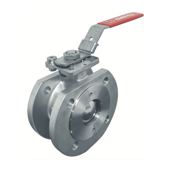
7. Sicherheitsdatenblätter beachten. 8. Sicherheitsvorschriften für die verwendeten Medien be- 3.2 Beschreibung achten. Der 2/2-Wege Metall-Kugelhahn GEMÜ B26 wird manuell betä- tigt. Er verfügt über einen kunststoffbeschichteten Handhebel. Bei Betrieb: Die Sitzdichtung besteht aus PTFE. 9. Dokument am Einsatzort verfügbar halten. -
Page 6: Gemü Conexo
Werkszeugnisse, Prüfdokumentationen und Wartungshistorien direkt verfügbar. Mit dem CONEXO Portal als zentrales Element lassen sich sämtliche Daten sammeln, verwalten und weiterverarbeiten. Weitere Informationen zu GEMÜ CONEXO finden Sie auf: www.gemu-group.com/conexo Anbringung des RFID-Chips Dieses Produkt besitzt in entsprechender Ausführung mit CO- NEXO einen RFID-Chip (1) zur elektronischen Wiedererken- nung. -
Page 7: Bestelldaten
5 Werkstoff Kugelhahn 1.4408 / CF8M (Körper, Anschluss), 1.4401 / SS316 (Kugel, Welle) 6 Dichtwerkstoff PTFE 7 Steuerfunktion Manuell betätigt, Handhebel, abschließbar 8 Sonderausführung ohne 9 CONEXO ohne integrierter RFID-Chip zur elektronischen Identifizierung und Rückverfolgbarkeit www.gemu-group.com 7 / 44 GEMÜ B26... -
Page 8: Technische Daten
80 100 120 140 160 180 200 Temperatur TS [°C] Druckstufe: DN 15 – 50: PN40 DN 65 – 100: PN16 Kv-Werte: Kv-Werte 1/2” 3/4” 1” 1¼” 1½” 2” 2½” 3” 4” 1700 Kv-Werte in m³/h GEMÜ B26 8 / 44 www.gemu-group.com... - Page 9 89,25 114,8 2½" 0,425 1,445 5,95 11,9 23,8 40,8 59,5 90,1 185,3 3" 0,595 2,975 15,3 29,75 76,5 114,8 174,3 263,5 4" 0,85 2,975 13,6 63,75 106,3 161,5 250,8 375,7 569,5 Kv-Werte in m³/h www.gemu-group.com 9 / 44 GEMÜ B26...
-
Page 10: Produktkonformitäten
7.5 Mechanische Daten Drehmomente: Losbrech- moment 1/2" 3/4" 1" 1¼" 1½" 2" 2½" 3" 4" Drehmomente in Nm Gewicht: Kugelhahn Gewicht 1/2" 3/4" 1" 1¼" 1½" 2" 2½" 11,9 3" 14,9 4" 20,4 Gewichte in kg GEMÜ B26 10 / 44 www.gemu-group.com... - Page 11 7 Technische Daten Gewicht: Handhebel Gewicht 1/2" 0,122 3/4" 0,122 1" 0,165 1¼" 0,165 1½" 0,398 2" 0,398 2½" 0,78 3" 0,78 4" 0,96 Gewichte in kg www.gemu-group.com 11 / 44 GEMÜ B26...
-
Page 12: Abmessungen
8 Abmessungen 8 Abmessungen 8.1 Kopfflansch 1/2“ 3/4“ 1“ 13,0 1¼“ 13,0 1½“ 15,0 2“ 16,0 2½“ 18,0 10,5 3“ 18,0 10,5 4“ 18,0 10,5 Maße in mm GEMÜ B26 12 / 44 www.gemu-group.com... -
Page 13: Körpermaße
119,0 85,0 4 x M16 214,0 130,6 93,0 4 x M16 214,0 139,0 107,0 4 x M16 258,0 162,0 119,0 8 x M16 298,0 174,0 132,0 8 x M16 270,0 186,0 Maße in mm www.gemu-group.com 13 / 44 GEMÜ B26... -
Page 14: Herstellerangaben
Passendes, funktionsfähiges und sicheres Werkzeug ver- 4. Lösungsmittel, Chemikalien, Säuren, Kraftstoffe u. ä. nicht ● wenden. mit GEMÜ Produkten und deren Ersatzteilen in einem Raum lagern. 1. Eignung des Produkts für den jeweiligen Einsatzfall sicher- stellen. 5. Kugelhähne in Position „offen“ lagern. -
Page 15: Einbau Bei Flanschanschluss
● Alle Sicherheits- und Schutzeinrichtungen wieder anbrin- 6. Kugelhahnflansch 2 und Rohrflansch 3 mit geeignetem gen bzw. in Funktion setzen. Dichtmaterial und passenden Schrauben verbinden. Dicht- material und Schrauben sind nicht im Lieferumfang enthal- ten. www.gemu-group.com 15 / 44 GEMÜ B26... -
Page 16: Inbetriebnahme
Kugelhahn mit arretiertem Handhebel 1 kann die Stellung mit einer geeigneten Schließvorrichtung (z.B. Vorhänge- schloss) in der Bohrung 5 oberhalb der Handhebelarretie- rung 3 im Handhebel 1 gesichert werden. Handhebel Kugelhahn geschlossen Kugelhahn geöffnet 1. Handhebel 1 in gewünschte Position bringen. GEMÜ B26 16 / 44 www.gemu-group.com... -
Page 17: Fehlerbehebung
Dichtungen korrekt montieren (siehe Kapitel „Dichtungen wechseln“) Falsche Dichtungen montiert Dichtungen wechseln (siehe Kapitel „Dichtungen wechseln“) Dichtungen defekt Dichtungen wechseln (siehe Kapitel „Dichtungen wechseln“) Ventilkörper undicht oder korrodiert Ventilkörper auf Beschädigungen prüfen, ggf. Ventilkörper tauschen www.gemu-group.com 17 / 44 GEMÜ B26... -
Page 18: Inspektion / Wartung
übernimmt GEMÜ keinerlei Haftung. Nehmen Sie im Zweifelsfall vor Inbetriebnahme Kontakt 14.1.1.1 Handhebel demontieren ● mit GEMÜ auf. 1. Geeignete Schutzausrüstung gemäß den Regelungen des Anlagenbetreibers berücksichtigen. 2. Anlage bzw. Anlagenteil stilllegen. 3. Gegen Wiedereinschalten sichern. 4. Anlage bzw. Anlagenteil drucklos schalten. - Page 19 7. Edelstahlbuchse 11 entnehmen. 4. Sechskantschraube 1 mit Unterlegscheibe 2 wieder hand- fest hineindrehen. 14.1.2 Dichtungen wechseln HINWEIS Nur Original GEMÜ Ersatzteile verwenden! ● Beim Bestellen von Ersatzteilen komplette Bestellnum- ● mer des Kugelhahns angeben. 1. Handhebel demontieren (siehe Kapitel "Handhebel demon- tieren").
- Page 20 ▶ Dichtungen 9: DN 15 – 80: 2 Stück DN 100: 3 Stück 16. O-Ring 7 von Welle abnehmen. 17. Dichtung 21 von Welle abnehmen. 18. Montage der Dichtungen und des Kugelhahns in umge- kehrter Reihenfolge. GEMÜ B26 20 / 44 www.gemu-group.com...
-
Page 21: Ausbau Aus Rohrleitung
Produkt keine Rücksendeerklärung bei, erfolgt keine Gut- schrift bzw. keine Erledigung der Reparatur, sondern eine kos- tenpflichtige Entsorgung. 1. Das Produkt reinigen. 2. Rücksendeerklärung bei GEMÜ anfordern. 3. Rücksendeerklärung vollständig ausfüllen. 4. Das Produkt mit ausgefüllter Rücksendeerklärung an GEMÜ schicken. -
Page 22: Konformitätserklärung Nach 2014/68/Eu (Druckgeräterichtlinie)
EN 1983, AD 2000 Hinweis für Produkte mit einer Nennweite ≤ DN 25: Die Produkte werden entwickelt und produziert nach GEMÜ eigenen Verfahrensanweisungen und Qualitätsstandards, welche die Forderungen der ISO 9001 und der ISO 14001 erfüllen. Die Produkte dürfen gemäß Artikel 4, Absatz 3 der Druckgeräterichtlinie 2014/68/EU keine CE-Kennzeichnung tragen. - Page 23 2 Safety information ............ 25 3 Product description ........... 25 Construction ............25 Description ............25 Function ............... 25 4 GEMÜ CONEXO ............26 5 Correct use ............... 26 6 Order data ..............27 7 Technical data ............28 Medium ..............28 Temperature ............
-
Page 24: General Information
Response(s) to tasks – Lists 1.3 Definition of terms Working medium The medium that flows through the GEMÜ product. 1.4 Warning notes Wherever possible, warning notes are organised according to the following scheme: SIGNAL WORD Type and source of the danger... -
Page 25: Safety Information
6. Define the areas of responsibility. 7. Observe the safety data sheets. The GEMÜ B26 2/2-way metal ball valve is manually operated. It has a plastic sleeved hand lever. The seat seal is made of 8. Observe the safety regulations for the media used. -
Page 26: Gemü Conexo
The CONEXO portal acts as a central element, helping to collect, manage and process all data. For further information on GEMÜ CONEXO please visit: www.gemu-group.com/conexo Installing the RFID chip In the corresponding design with CONEXO, this product has an RFID chip (1) for electronic recognition. -
Page 27: Order Data
1.4408 / CF8M (body, connection), 1.4401 / SS316 (ball, shaft) 6 Seal material PTFE 7 Control function Manually operated, hand lever, lockable 8 Special version without 9 CONEXO without Integrated RFID chip for electronic identification and traceability www.gemu-group.com 27 / 44 GEMÜ B26... -
Page 28: Technical Data
DN 15 – 50: PN40 DN 65 – 100: PN16 Kv values: Kv values 1/2” 12.8 3/4” 29.1 1” 47.8 1¼” 1½” 2” 213.7 2½” 273.3 3” 495.3 4” 871.1 Kv values in m³/h GEMÜ B26 28 / 44 www.gemu-group.com... - Page 29 89.25 114.8 2½" 0.425 1.445 5.95 11.9 23.8 40.8 59.5 90.1 185.3 3" 0.595 2.975 15.3 29.75 76.5 114.8 174.3 263.5 4" 0.85 2.975 13.6 63.75 106.3 161.5 250.8 375.7 569.5 Kv values in m³/h www.gemu-group.com 29 / 44 GEMÜ B26...
-
Page 30: Product Conformities
Torques: Breakaway torque 1/2" 3/4" 1" 1¼" 1½" 2" 2½" 3" 4" Torques in Nm Weight: Ball valve Weight 1/2" 3/4" 1" 1¼" 1½" 2" 2½" 11.9 3" 14.9 4" 20.4 Weights in kg GEMÜ B26 30 / 44 www.gemu-group.com... - Page 31 7 Technical data Weight: Hand lever Weight 1/2" 0.122 3/4" 0.122 1" 0.165 1¼" 0.165 1½" 0.398 2" 0.398 2½" 0.78 3" 0.78 4" 0.96 Weights in kg www.gemu-group.com 31 / 44 GEMÜ B26...
-
Page 32: Dimensions
8 Dimensions 8 Dimensions 8.1 Top flange 1/2“ 3/4“ 1“ 13.0 1¼“ 13.0 1½“ 15.0 2“ 16.0 2½“ 18.0 3“ 18.0 10.5 4“ 18.0 10.5 Dimensions in mm GEMÜ B26 32 / 44 www.gemu-group.com... -
Page 33: Body Dimensions
119.0 85.0 4 x M16 214.0 130.6 93.0 4 x M16 214.0 139.0 107.0 4 x M16 258.0 162.0 119.0 8 x M16 298.0 174.0 132.0 8 x M16 270.0 186.0 Dimensions in mm www.gemu-group.com 33 / 44 GEMÜ B26... -
Page 34: Manufacturer's Information
Use appropriate, functional and safe tools. 4. Do not store solvents, chemicals, acids, fuels or similar ● fluids in the same room as GEMÜ products and their spare 1. Ensure the product is suitable for the relevant application. parts. 2. Check the technical data of the product and the materials. -
Page 35: Installation With Flanged Connections
6. Connect the ball valve flange 2 and piping flange 3 using ● Re-attach or reactivate all safety and protective devices. appropriate sealing material and matching bolting. Sealing material and bolts are not included in the scope of deliv- ery. www.gemu-group.com 35 / 44 GEMÜ B26... -
Page 36: Commissioning
(e.g. padlock) in the bolt hole 5 above the hand lever locking device 3 in the hand lever 1. Hand lever Ball valve closed Ball valve open 1. Move the hand lever 1 to the desired position. GEMÜ B26 36 / 44 www.gemu-group.com... -
Page 37: Troubleshooting
Wrong seals mounted Replace seals (see chapter "Replacing the seals") Seals faulty Replace seals (see chapter "Replacing the seals") Valve body leaks or is corroded Check valve body for damage, replace valve body if necessary www.gemu-group.com 37 / 44 GEMÜ B26... -
Page 38: Inspection/Maintenance
Servicing and maintenance work must only be performed ● ð Groove in piping direction: by trained personnel. Ball valve open. Do not extend hand lever. GEMÜ shall assume no liability ● whatsoever for damages caused by improper handling or 14.1.1 Replacing the hand lever third-party actions. - Page 39 4. Screw in the hexagon head bolt 1 with washer 2 again until hand tight. 14.1.2 Replacing the seals NOTICE Only use genuine GEMÜ spare parts. ● When ordering spare parts, specify the complete order ● number of the ball valve.
- Page 40 DN 15–80: 2 pieces DN 100: 3 pieces 16. Remove the O-ring 7 from the shaft. 17. Remove the gasket 21 from the shaft. 18. Mount the seals and the ball valve in reverse order. GEMÜ B26 40 / 44 www.gemu-group.com...
-
Page 41: Removal From Piping
Returned goods can be processed only when this note is completed. If no return delivery note is included with the product, GEMÜ cannot process credits or repair work but will dispose of the goods at the operator's expense. -
Page 42: Declaration Of Conformity According To 2014/68/Eu (Pressure Equipment Directive)
EN 1983, AD 2000 Note for products with a nominal size ≤ DN 25: The products are developed and produced according to GEMÜ process instructions and quality standards which comply with the requirements of ISO 9001 and ISO 14001. According to Article 4, Paragraph 3 of the Pressure Equipment Directive 2014/68/EU these products must not be identified by a CE-label. - Page 43 GEMÜ B26 43 / 44 www.gemu-group.com...
- Page 44 GEMÜ Gebr. Müller Apparatebau GmbH & Co. KG Subject to alteration *88714681* Fritz-Müller-Straße 6-8, 74653 Ingelfingen-Criesbach, Germany 09.2020 | 88714681 Phone +49 (0)7940 123-0 · info@gemue.de www.gemu-group.com...
Need help?
Do you have a question about the B26 and is the answer not in the manual?
Questions and answers