
Related Manuals for GEM 612 Series


Summary of Contents for GEM 612 Series
- Page 1 Membranventil Metall, DN 10 - 20 Diaphragm Valve Metal, DN 10 - 20 ORIGINAL EINBAU- UND MONTAGEANLEITUNG INSTALLATION, OPERATING AND MAINTENANCE INSTRUCTIONS 612_us...
-
Page 2: Table Of Contents
Funktion des GEMÜ-Ventils: Allgemeine Sicherheitshinweise 2 Sachgerechter Transport und Lagerung. Hinweise für Service- Installation und Inbetriebnahme durch und Bedienpersonal eingewiesenes Fachpersonal. Warnhinweise Bedienung gemäß dieser Einbau- und Verwendete Symbole Montageanleitung. Begriffsbestimmungen Ordnungsgemäße Instandhaltung. Vorgesehener Einsatzbereich Auslieferungszustand Korrekte Montage, Bedienung und Wartung... -
Page 3: Warnhinweise
Sicherheitsdatenblätter bzw. die für 2.3 Verwendete Symbole die verwendeten Medien geltenden Sicherheitsvorschriften unbedingt Gefahr durch heiße Oberflächen! beachten! Gefahr durch ätzende Stoffe! Bei Unklarheiten: Bei nächstgelegener GEMÜ- Verkaufsniederlassung nachfragen. Quetschgefahr! 2.2 Warnhinweise Hand: Beschreibt allgemeine Hinweise und Empfehlungen. Warnhinweise sind, soweit möglich, nach folgendem Schema gegliedert: Punkt: Beschreibt auszuführende... -
Page 4: Begriffsbestimmungen
DIN 11850 ASME BPE EN ISO Reihe 1 Reihe 2 Reihe 3 1127 Code 0 Code 16 Code 17 Code 18 Code 59 Code 60 Kv-Werte ermittelt gemäß Norm IEC 534, Eingangsdruck 6 bar, ∆p 1 bar, Ventilkörperwerkstoff Edelstahl und Weichelastomermembrane. MG = Membrangröße 612_us 4 / 32... -
Page 5: Bestelldaten
Bestelldaten Gehäuseform Code Ventilkörperwerkstoff Code Behälterkörper 1.4435 - BN2 (CF3M) - Feinguss Fe<0,5% Durchgang 1.4435 (ASTM A 351 CF3M, ≙ 316L) Feinguss Mehrwegeausführung 1.4435 (316L), Schmiedekörper T-Körper 1.4435 (BN2), Schmiedekörper Fe<0,5% * Abmessungen siehe Broschüre T-Ventile Membranwerkstoff Code ** Abmessungen und Ausführungen auf Anfrage bzw. auf Kundenwunsch Anschlussart Code EPDM... -
Page 6: Herstellerangaben
Siehe Kapitel 6 "Technische Daten". ¬ sicheres Werkzeug benutzen. 11.1 Montage des 9 Funktionsbeschreibung Membranventils GEMÜ 612 ist ein Metall-Membranventil mit Durchgangs-, T- oder Behälterboden-Ablass- WARNUNG körper bzw. Ausführung in Mehrwegeausfüh- Unter Druck stehende Armaturen! rung. Antriebsgehäuse und -mechanik sind P Gefahr von schwersten Verletzungen komplett aus Edelstahl. - Page 7 Ventilkörpers demontieren (siehe Schutzmaßnahmen vermeiden. Kapitel 12.1). Montagearbeiten nur durch geschultes 3. Schweißstutzen abkühlen lassen. ¬ Fachpersonal. 4. Ventilkörper und Antrieb mit Membrane Geeignete Schutzausrüstung gemäß wieder zusammen bauen (siehe Kapitel ¬ den Regelungen des Anlagenbetreibers 12.4). berücksichtigen. Montage bei Clampanschluss: Installationsort: Bei Montage der Clampanschlüsse...
-
Page 8: Bedienung
Ventil (mit Membrane und Ventilkörper) und in kaltem Zustand! Ventil offen Ventil geschlossen VORSICHT Zum Schutz der Dichtmembrane verfügen die Ventile der Baureihe GEMÜ 612 serien- Heißes Handrad während mäßig über eine mechanisch einstellbare Betrieb! Schließbegrenzung. P Verbrennungen! Handrad nur mit Schutz- Standardeinstellung: ¬... - Page 9 2. Arretierungsschraube 6 lösen, heraus 6. Handrad H 180° verdreht auf den drehen und entfernen. Zweiflach der Ventilspindel aufsetzen. 3. Handrad H nach oben abziehen. 7. Ventil behutsam mit Handrad H schließen ("ZU"). 8. Handrad H von Ventilspindel abziehen. 4. Einstellring 4 lösen, heraus drehen und entfernen.
-
Page 10: Montage / Demontage Von Ersatzteilen
1. Antrieb A in Offen-Position bringen. 3. Alle Teile auf Beschädigungen prüfen. 2. Antrieb A vom Ventilkörper 1 4. Beschädigte Teile austauschen (nur demontieren. Originalteile von GEMÜ verwenden). 3. Antrieb A in Geschlossen-Position bringen. 12.3 Montage Membrane 12.3.1 Allgemeines Wichtig: Für Ventil passende Membrane... -
Page 11: Montage Der Konkav-Membrane
5. Kontrollieren ob Membrandom in 45° Druckstückaussparung liegt. 6. Bei Schwergängigkeit Gewinde prüfen, beschädigte Teile austauschen (nur Originalteile von GEMÜ verwenden). 7. Beim Verspüren eines deutlichen Widerstands Membrane soweit zurück- schrauben, bis Membran-Lochbild mit Antriebs-Lochbild übereinstimmt. Das Druckstück ist lose. -
Page 12: Inbetriebnahme
Fremdeinwirkung entstehen, übernimmt prüfen! GEMÜ keinerlei Haftung. Dichtheitsprüfung nur mit ge- ¬ Nehmen Sie im Zweifelsfall vor eigneter Schutzausrüstung. ¬ Inbetriebnahme Kontakt mit GEMÜ auf. VORSICHT 1. Geeignete Schutzausrüstung gemäß den Regelungen des Anlagenbetreibers Gegen Leckage vorbeugen! berücksichtigen. Schutzmaßnahmen gegen ¬ 2. Anlage bzw. Anlagenteil stilllegen. -
Page 13: Demontage
Ventil autokla- Hinweis zur Richtlinie 94/9/EG viert wird. (ATEX Richtlinie): Ein Beiblatt zur Richtlinie 94/9/EG 15 Demontage liegt dem Produkt bei, sofern es gemäß ATEX bestellt wurde. Demontage erfolgt unter den gleichen Vorsichtsmaßnahmen wie die Montage. Hinweis zur Mitarbeiter- Membranventil demontieren (siehe schulung: ¬... -
Page 14: Fehlersuche / Störungsbehebung
19 Fehlersuche / Störungsbehebung Fehler Möglicher Grund Fehlerbehebung Medium entweicht aus Absperrmembrane auf Beschädigungen Leckagebohrung (siehe Absperrmembrane defekt prüfen, ggf. Membrane tauschen Schnittbild Kapitel 20) Antrieb defekt Antrieb austauschen Ventil öffnet nicht bzw. nicht Absperrmembrane nicht korrekt Antrieb demontieren, Membranmontage vollständig montiert prüfen, ggf. - Page 15 20 Schnittbild und Ersatzteile Leckagebohrung Pos. Benennung Bestellbezeichnung Ventilkörper K612... Membrane 600...M Schraube 612...S30... Scheibe Antrieb 9612... 612_us 15 / 32...
- Page 16 - and by any 12.4 Bonnet mounting additional assembly personnel. on the valve body Commissioning Important: Inspection and servicing The GEMÜ valve is sold to Disassembly sophisticated users. Training Disposal regarding safety issues must be Returns undertaken by each user. Information...
-
Page 17: Warning Notes
Danger - bodily injury! Strictly observe the safety data sheets or the safety regulations valid for the media used. Hand: indicates general notes and recommendations. In case of uncertainty Consult the nearest GEMÜ sales office. Point: indicates the tasks to be ¬ performed. Arrow: indicates the response(s) to 2.2 Warning notes tasks. Wherever possible, warning notes are... -
Page 18: Definition Of Terms
To avoid malfunction which could instructions. cause injury or damage, do not paint the bolts and plastic parts of the diaphragm valve! 5 Delivery condition The GEMÜ diaphragm valve is supplied as a separately packed component. Technical data Nominal Max. operating Valve weight*... -
Page 19: Order Data
7 Order data Body configuration Code Valve body material Code Tank valve body 1.4435 - BN2 (CF3M), investment casting Fe<0.5% 2/2-way body 1.4435 (ASTM A 351 CF3M, ≙ 316L) investment casting Multi-port design 1.4435 (316L), forged body T body 1.4435 (BN2), forged body Fe<0.5% * For dimensions see T Valves brochure ** Dimensions and versions on request or according to customer Diaphragm material... -
Page 20: Manufacturer's Information
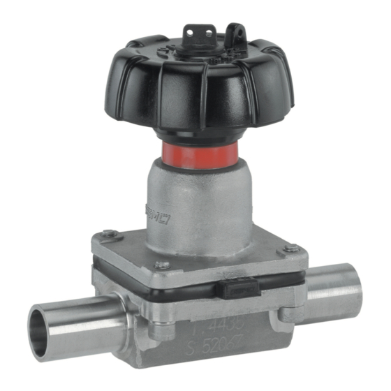
Manufacturer’s information Function description GEMÜ 612 is a metal diaphragm valve with a 2/2-way, T or tank bottom valve body or in Transport multi-port design. Bonnet and internals are made all of stainless steel. An integral optical Only transport the diaphragm valve position indicator and a seal adjuster are ¬... -
Page 21: Assembling The Diaphragm Valve
11.1 Assembling the Installation location: diaphragm valve CAUTION Do not apply external force to the valve. WARNING ¬ Choose the installation location so that ¬ The equipment is subject to the valve cannot be used as a foothold. pressure! Lay the pipeline so that the valve body ¬... -
Page 22: Operation
(with diaphragm and valve body) 11.2 Operation and in a cold condition. Optical position indicator The valves type GEMÜ 612 have a mechanical seal adjuster as standard to protect the sealing diaphragm. Standard setting: The valve is sealed when the handwheel is completely closed (turned fully clockwise). - Page 23 5. Dependent on the operating conditions, regrease the threaded spindle, especially a valve that is autoclaved. 10. Push handwheel H in its original position GEMÜ recommends the grease Boss- on the double flats of the valve spindle Fluorine Y 108/00 (99099484). 612_us...
-
Page 24: Assembly / Disassembly Of Spare Parts
/ or the regulatory codes contamination (do not damage and provisions applicable for this parts). Check parts for potential application. damage, replace if necessary (only use genuine parts from GEMÜ). Important: Dependent operating If the diaphragm is not screwed into conditions, regrease the threaded... -
Page 25: Mounting A Concave Diaphragm
6. If it is difficult to screw it in, check the The compressor is loose. thread, replace damaged parts (only use genuine parts from GEMÜ). Anti-twist protection of the spindle at the 7. When clear resistance is felt turn back... -
Page 26: Commissioning
Protect against leakage! by improper handling or third-party Provide precautionary measures ¬ actions. against exceeding the maximum In case of doubt, contact GEMÜ before permitted pressures caused by ¬ commissioning. pressure surges (water hammer). 612_us 26 / 32... -
Page 27: Disassembly
Returns must be made with a completed 2. Shut off plant or plant component. ¬ declaration of return (included). Secure against re-commissioning. If not completed, GEMÜ cannot process 4. Depressurize the plant or plant credits or component. repair work but will dispose of the goods at the operator's The operator must carry out regular expense. -
Page 28: Troubleshooting / Fault Clearance
Troubleshooting / Fault clearance Fault Possible cause Fault clearance Medium escapes from leak Check valve diaphragm for damage, detection hole (see sectional Valve diaphragm faulty replace diaphragm if necessary drawing chapter 20) Bonnet faulty Replace bonnet Valve doesn't open or doesn't Remove bonnet, check diaphragm open fully Valve diaphragm incorrectly mounted mounting, replace if necessary... -
Page 29: Sectional Drawing
20 Sectional drawing and spare parts Leak detection hole Item Name Order description Valve body K612... Diaphragm 600...M Bolt 612...S30... Washer Bonnet 9612... 612_us 29 / 32... - Page 30 Rücksendeerklärung (Kopiervorlage) Gesetzliche Bestimmungen, der Schutz der Umwelt und des Personals erfordern es, diese Erklärung vollständig ausgefüllt und unterschrieben den Versandpapieren beizulegen. Wenn diese Erklärung nicht vollständig ausgefüllt ist oder den Versandpapieren nicht beigelegt ist wird Ihre Rücksendung nicht bearbeitet! Wurde das Ventil / Gerät mit giftigen, ätzenden, brennbaren, aggressiven oder wassergefährdenden Medien betrieben, alle mediumsberührten Teile sorgfältig entleeren, dekontaminieren und spülen.
-
Page 31: Goods Return Declaration
Goods return declaration (copy specimen) Legal regulations for the protection of the environment and personnel require that you include the completed and signed goods return declaration with your dispatch documents. If this declaration is not completed or not included with the dispatch documents, your return will not be processed! If the valve / device was operated with poisonous, corrosive, flammable, aggressive or water- endangering media, all medium wetted parts must be emptied carefully, decontaminated and rinsed. - Page 32 VENTIL-, MESS- UND REGELSYSTEME VALVES, MEASUREMENT AND CONTROL SYSTEMS GEMÜ Gebr. Müller Apparatebau GmbH & Co. KG · Fritz-Müller-Str. 6-8 · D-74653 Ingelfi ngen-Criesbach Telefon +49(0)7940/123-0 · Telefax +49(0)7940/123-192 · info@gemue.de ·www.gemue.de...
Need help?
Do you have a question about the 612 Series and is the answer not in the manual?
Questions and answers