
Subscribe to Our Youtube Channel
Related Manuals for GEM B54


Summary of Contents for GEM B54
- Page 1 GEMÜ B54 Motorized ball valve Operating instructions further information webcode: GW-B54...
- Page 2 All rights including copyrights or industrial property rights are expressly reserved. Keep the document for future reference. © GEMÜ Gebr. Müller Apparatebau GmbH & Co. KG 27.11.2020 GEMÜ B54 2 / 43 www.gemu-group.com...
-
Page 3: Table Of Contents
4 GEMÜ CONEXO ............5 Correct use ............... 6 Order data ..............Ball valve with GEMÜ 9428, 9468 actuator ..Ball valve with J+J actuator ....... Ball valve with Bernard actuator ......11 7 Ball valve technical data ..........13 Medium .............. -
Page 4: General Information
Symbol Meaning 1.3 Definition of terms Danger of explosion! Working medium The medium that flows through the GEMÜ product. Control medium Corrosive chemicals! The medium whose increasing or decreasing pressure causes the GEMÜ product to be actuated and operated. Control function Hot plant components! The possible actuation functions of the GEMÜ... -
Page 5: Product Description
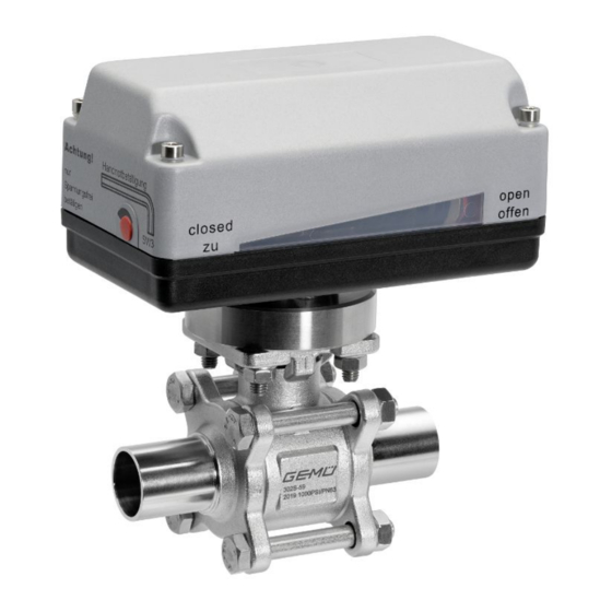
6. Define the areas of responsibility. 7. Observe the safety data sheets. The GEMÜ B54 3-piece 2/2-way metal ball valve is motorized. It has a plastic actuator housing and is particularly suitable 8. Observe the safety regulations for the media used. -
Page 6: Correct Use
The product is suitable for installation in piping and for con- For further information on GEMÜ CONEXO please visit: trolling a media flow. The operating conditions according to www.gemu-group.com/conexo the technical data apply to the media to be controlled. -
Page 7: Order Data
6 Order data 6 Order data 6.1 Ball valve with GEMÜ 9428, 9468 actuator The order data provide an overview of standard configurations. Please check the availability before ordering. Other configurations available on request. Order codes 1 Type Code 8 Continuation of Control module... - Page 8 TFM 1600 (FDA certification) 7 Voltage/Frequency 24 VDC 8 Control module ON/OFF actuator 9 Actuator version 1015 GEMÜ actuator, motorized, size 1, operating time 11 s, torque 15 Nm, supply voltage B1, C1 10 CONEXO without GEMÜ B54 8 / 43 www.gemu-group.com...
-
Page 9: Ball Valve With J+J Actuator
Code without 24-240V AC/DC Integrated RFID chip for electronic identification and traceability 8 Control module Code ON/OFF 3-position actuator, additional potential- free limit switches ON/OFF actuator, 2 additional potential-free limit switches, Class A (EN15714-2) www.gemu-group.com 9 / 43 GEMÜ B54... - Page 10 8 Control module ON/OFF actuator, 2 additional potential-free limit switches, Class A (EN15714-2) 9 Actuator version J4C20 J+J actuator, motorized, type J4C, operating time 10 s, torque 20 Nm, heating, IP 67 10 CONEXO without GEMÜ B54 10 / 43 www.gemu-group.com...
-
Page 11: Ball Valve With Bernard Actuator
RAL1014, IP 68 switches, BERNARD actuator, motorized, type AQ25, operat- BC25 additional potential-free torque switches, Class A ing time 30s, torque 250Nm, (EN15714-2) 2 additional limit switches, heating, manual over- ride, aluminium housing, RAL1014, IP 68 www.gemu-group.com 11 / 43 GEMÜ B54... - Page 12 ON/OFF actuator, 2 additional potential-free limit switches, Class A (EN15714-2) 9 Actuator version BC1L BERNARD actuator, motorized, type AQ1L, operating time 13s, torque 15Nm, 2 additional limit switches, heating, manual override, aluminium housing, RAL5002, IP 67 10 CONEXO without GEMÜ B54 12 / 43 www.gemu-group.com...
-
Page 13: Ball Valve Technical Data
Code 17: Spigot EN 10357 series A (formerly DIN 11850 series 2)/DIN 11866 series A Code 59: Spigot ASME BPE Code 60: Spigot ISO 1127/EN 10357 series C/DIN 11866 series B Code 80: Clamp ASME BPE, face-to-face dimension FTF ASME BPE www.gemu-group.com 13 / 43 GEMÜ B54... -
Page 14: Product Conformities
1¼" 1½" 2" 2½" 3" 4" Free of oil and grease incl. 25% safety Torques in Nm 1) Seal material Code 5H: TFM 1600 (FDA certification), cavity filled Code 5T: TFM 1600 (FDA certification) GEMÜ B54 14 / 43 www.gemu-group.com... -
Page 15: Technical Data Of Actuator
Code 59: Spigot ASME BPE Code 60: Spigot ISO 1127/EN 10357 series C/DIN 11866 series B Code 80: Clamp ASME BPE, face-to-face dimension FTF ASME BPE 8 Technical data of actuator 8.1 GEMÜ 9428, 9468 actuators 8.1.1 Mechanical data Weight: GEMÜ 9428 Supply voltage 24 V / 100-250 V 2.4 kg... - Page 16 T 1A 5x20 mm GEMÜ 9468 Internal for functional module 0x Actuator version 2070: MT 6.3 A Actuator version 4100, 4200: MT 10.0 A Motor protective system by customer, see "Recommended motor protection" GEMÜ B54 16 / 43 www.gemu-group.com...
-
Page 17: Bernard, J+J Actuators
Set current 2.20 1.70 0.60 0.45 Current data in A GEMÜ 9468 Motor protection switch Siemens 3RV 1011-1FA10 type: Set current: 4.0 A 8.2 Bernard, J+J actuators Note: For technical data see manufacturer's original datasheets www.gemu-group.com 17 / 43 GEMÜ B54... -
Page 18: Dimensions
9 Dimensions 9 Dimensions 9.1 Actuator dimensions 9.1.1 GEMÜ 9428, 9468 actuators 9.1.1.1 Actuator version 1006, 1015, 2006, 2015 * Standard with supply voltage code O4 Actuator ver- sion 1006, 1015 2006, 2015 Dimensions in mm 9.1.1.2 Actuator version 3035, 3055... - Page 19 9 Dimensions 9.1.1.3 Actuator version 4100, 4200 277,5 Dimensions in mm 9.1.2 Bernard, AUMA, J+J actuators For more detailed information on third-party actuators, refer to the manufacturers' documentation www.gemu-group.com 19 / 43 GEMÜ B54...
- Page 20 42.0 50.0 11.0 13.0 1½“ 50.0 70.0 14.0 15.0 2“ 50.0 70.0 14.0 16.0 2½“ 50.0 70.0 17.0 18.0 3“ 70.0 102.0 17.0 18.0 10.5 4“ 102.0 125.0 17.0 18.0 10.5 Dimensions in mm GEMÜ B54 20 / 43 www.gemu-group.com...
- Page 21 4 x M14 66.0 70.0 131.5 254.0 82.0 86.0 92.0 4 x M14 81.0 85.0 158.0 280.0 96.0 92.0 102.0 4 x M16 100.0 104.0 198.5 308.0 122.0 93.0 132.0 6 x M20 Dimensions in mm www.gemu-group.com 21 / 43 GEMÜ B54...
- Page 22 63.5 1.65 126.0 254.1 77.1 88.5 89.0 4 x M14 72.9 76.2 1.65 150.0 276.9 91.7 92.6 98.0 4 x M16 97.4 101.6 187.5 304.9 118.3 93.3 130.0 6 x M16 Dimensions in mm GEMÜ B54 22 / 43 www.gemu-group.com...
- Page 23 4 x M14 72.1 76.1 131.5 254.0 82.0 86.0 92.0 4 x M14 84.3 88.9 158.0 280.0 96.0 92.0 102.0 4 x M16 109.7 114.3 198.5 308.0 122.0 93.0 132.0 6 x M20 Dimensions in mm www.gemu-group.com 23 / 43 GEMÜ B54...
- Page 24 77.4 1.65 126.0 171.5 77.1 47.2 89.0 4 x M14 72.9 90.9 1.65 150.0 196.3 91.7 52.3 98.0 4 x M16 97.4 118.9 187.5 241.3 118.3 61.5 130.0 6 x M16 Dimensions in mm GEMÜ B54 24 / 43 www.gemu-group.com...
-
Page 25: Manufacturer's Information
Provide precautionary measures against exceeding the ● 4. Do not store solvents, chemicals, acids, fuels or similar maximum permitted pressures caused by pressure fluids in the same room as GEMÜ products and their spare surges (water hammer). parts. CAUTION 5. Store the ball valves in the "open" position. -
Page 26: Installation With Butt Weld Spigots
14. Flow direction and installation position are optional. 2. Align the pipes 1 and 4 on the left and right with the butt weld spigots 2 and 3, and attach them to the spigots. GEMÜ B54 26 / 43 www.gemu-group.com... -
Page 27: Installation With Clamp Connections
9. Tighten the nuts diagonally, counterhold with a wrench. 4. Connect the clamp of the ball valve and the clamp of the piping with the appropriate sealing clamp 4. 5. Only use connector elements made of approved materials! www.gemu-group.com 27 / 43 GEMÜ B54... -
Page 28: Electrical Connection
Uv-, direction of travel OPEN PE, protective earth conductor Connection diagram Limit switch OPEN External wiring Motor + − PE Limit switch CLOSED Actuator CLOSED Direction of travel CLOSED OPEN Direction of travel OPEN GEMÜ B54 28 / 43 www.gemu-group.com... -
Page 29: Connection And Wiring Diagram - Actuator Version 2070, 4100, 4200
The potential must be assigned by the user. When the OPEN and CLOSED switches are operated simultaneously the actuator "CLOSES". 12.2.1.1.3 Connection diagram Motor protection switch Direction recommended switch CLOSED L1/Uv+ External wiring OPEN N/Uv- Connection assignment X1 www.gemu-group.com 29 / 43 GEMÜ B54... -
Page 30: Limit Switches
3. Undo screws 2. 4. Remove the cover of the actuator 3. 5. Undo the screws on the corresponding limit switch (4 = "CLOSED", 5 = "OPEN"). 6. Move limit switches to the desired position. 7. Tighten limit switch screws. GEMÜ B54 30 / 43 www.gemu-group.com... -
Page 31: Setting The Limit Switch For 2070, 4100, 4200
24 V DC, 24 V AC up to 250 V AC or operated directly via a PLC. • An electronic current limitation limits the torque. • For the above actuator types (except for code 2070), overall height 2 applies. www.gemu-group.com 31 / 43 GEMÜ B54... -
Page 32: Operation
Attention! Manual override Only actuate when power is switched off Open Closed Actuator versions 4100, 4200 Actuator versions 1015, 2015 open closed emergency OPEN operation CLOSED Open Closed Actuator version 3035 GEMÜ B54 32 / 43 www.gemu-group.com... -
Page 33: Setting The Limit Switches
ð Limit switches for signal and motor are already preset. that shuts off power to the actuator. The GEMÜ 9428 motorized actuator is delivered in open posi- tion. The following drawings differ depending on the actuator ver- sion! 1. - Page 34 6. Move limit switches to the desired position. 7. Tighten limit switch screws. 8. Put on cover of actuator 3. 9. Tighten cover 3. 10. Put on protective caps 1. ð Limit switches are set. GEMÜ B54 34 / 43 www.gemu-group.com...
-
Page 35: Troubleshooting
Valve body leaks or is corroded Check valve body for damage, replace valve body if necessary Bolts of the ball valve body are loose Retighten bolts No flow Ball incorrectly adjusted Turn ball to the correct position www.gemu-group.com 35 / 43 GEMÜ B54... -
Page 36: Inspection/Maintenance
CAUTION Servicing and maintenance work must only be performed ● by trained personnel. Do not extend hand lever. GEMÜ shall assume no liability ● whatsoever for damages caused by improper handling or third-party actions. In case of doubt, contact GEMÜ prior to commissioning. -
Page 37: Spare Parts
17.1 Spare parts Item Name Order designation Ball valve body BB04 Seat seal (2 x) Flange seals (2x) Sealing washer spindle O-ring BB04 SDS V-ring spindle packing Actuator See actuator designation. Dependent on the actuator version. www.gemu-group.com 37 / 43 GEMÜ B54... -
Page 38: Replacing The Actuator
▶ Clean all parts of contamination (do not damage the parts during cleaning) following removal. Check parts for potential damage; replace if necessary (only use genuine parts from GEMÜ). 17.2.3 Replacement of spare parts NOTICE If a spare part must be replaced, it is recommended to ●... - Page 39 17.2.4 Installing the ball valve body NOTICE ▶ Installation is performed in reverse order as for disas- sembly (see chapter "Disassembling the ball valve body"). www.gemu-group.com 39 / 43 GEMÜ B54...
-
Page 40: 19 Disposal
Returned goods can be processed only when this note is completed. If no return delivery note is included with the product, GEMÜ cannot process credits or repair work but will dispose of the goods at the operator's expense. -
Page 41: Declaration Of Incorporation According To 2006/42/ Ec (Machinery Directive)
21 Declaration of Incorporation according to 2006/42/EC (Machinery Directive) Declaration of Incorporation according to the EC Machinery Directive 2006/42/EC, Annex II, 1.B for partly completed machinery GEMÜ Gebr. Müller Apparatebau GmbH & Co. KG Fritz-Müller-Straße 6-8 74653 Ingelfingen-Criesbach, Germany declare that the following product Make GEMÜ... -
Page 42: Declaration Of Conformity According To 2014/30/Eu (Emc Directive)
22 Declaration of conformity according to 2014/30/EU (EMC Directive) EU Declaration of Conformity in accordance with 2014/30/EU (EMC Directive) GEMÜ Gebr. Müller Apparatebau GmbH & Co. KG Fritz-Müller-Straße 6-8 74653 Ingelfingen-Criesbach, Germany declare that the product listed below complies with the safety requirements of the EMC Directive 2014/30/EU. - Page 43 Subject to alteration GEMÜ Gebr. Müller Apparatebau GmbH & Co. KG *88736569* Fritz-Müller-Straße 6–8, 74653 Ingelfingen-Criesbach, Germany 11.2020 | 88736569 Phone +49 (0) 7940 1230 · info@gemue.de www.gemu-group.com...
Need help?
Do you have a question about the B54 and is the answer not in the manual?
Questions and answers