Bender ISOMETER isoRW685W-D Manual
Insulation monitoring device for railway systems
Hide thumbs
Also See for ISOMETER isoRW685W-D:
- Manual (60 pages) ,
- Quick start manual (8 pages) ,
- Manual (87 pages)

Related Manuals for Bender ISOMETER isoRW685W-D


Summary of Contents for Bender ISOMETER isoRW685W-D
- Page 1 ISOMETER® isoRW685W-D(-B) Installationsüberwachungsgerät für Bahnanwendungen Insulation monitoring device for Railway systems isoRW685W-D-x_D00419_00_Q_DEEN/02.2020 Kurzanleitung/Quickstart DE/EN...
- Page 2 D00178 AC 24…240 V via A1/+, A2/- (50…400 Hz) isoRW685W-D-B B91067022W D00419 Handbuch/Quickstart download: www.bender.de/service-support/downloadbereich Bestimmungsgemäße Verwendung Intended use Das ISOMETER® isoRW685W-D-x überwacht den The ISOMETER® isoRW685W-D-x monitors the insula- Isolationswiderstand von ungeerdeten AC/DC- tion resistance of unearthed AC/DC main circuits (IT Hauptstromkreisen (IT-Systemen) mit Netznenn- systems) with mains voltages of AC 0…690 V or...
-
Page 3: Montage
ISOMETER® isoRW685W-D(-B) Montage Mounting 1 0 8 m m 1 1 0 20 mm 0 mm 0 mm 20 mm Ø M4 Anschluss Connection Verdrahten Sie das Gerät gemäß Anschlussplan. Wire up the device according to the wiring diagram Beachten Sie dabei die technischen Daten. Montieren taking account of the technical data. - Page 4 ISOMETER® isoRW685W-D(-B) 3(N)AC Anschluss Legende zu den Anschlussbildern Klemme Anschlüsse A1/+ A2/- ** Stromversorgung, = 24…240 V (50…400Hz) L1/+, L2, L3/- Anschlüsse an das zu überwachende Netz AC, 0…690 V AC, 0…600 V für UL-Anwendungen DC, 0…1000 V L3/- A1/+ A2/–...
- Page 5 ISOMETER® isoRW685W-D(-B) Connection L3/- A1/+ A2/– L1/+ Legend to terminal diagrams Terminal Connections A1/+ A2/- ** Power supply, = 24…240 V (50…400 Hz) L1/+, L2, L3/- Connections to the system to be monitored AC, 0…690 V AC, 0…600 V für UL applications DC, 0…1000 V KE E Connection to ground...
-
Page 6: Inbetriebnahme Des Geräts
ISOMETER® isoRW685W-D(-B) Inbetriebnahme des Geräts Commissioning of the device 1. Prüfen auf korrekten Anschluss des ISOMETER®s an 1. Check that the ISOMETER® is properly connected to das zuüberwachende Netz. the system to be monitored. 2. Versorgungsspannung für ISOMETER® zuschalten 2. Connect the supply voltage to the ISOMETER® 3. -
Page 7: Factory Settings
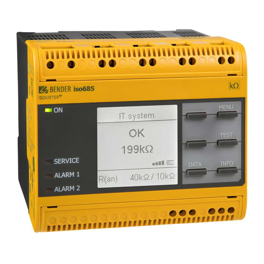
ISOMETER® isoRW685W-D(-B) TEST IT-System Insulation fault √ Measurement √ Coupling 120 k √ Earth connection √ Outputs 100% R(an) 40 k / 10 k R(an) 40 k / 10 k Das Profil „Leistungskreise“ ist für IT-Systeme The profile „Power circuits“ is suitable for IT sys- voreingestellt. -
Page 8: Technische Daten
Nachdruck und Vervielfältigung Reprinting and duplicating nur mit Genehmigung des Herausgebers. only with permission of the publisher. Bender GmbH & Co. KG Bender GmbH & Co. KG Postfach 1161 • 35301 Grünberg • Deutschland PO Box 1161 • 35301 Gruenberg • Germany Londorfer Str.
Need help?
Do you have a question about the ISOMETER isoRW685W-D and is the answer not in the manual?
Questions and answers