Advertisement
CY8CKIT-036 THERMAL MANAGEMENT KIT
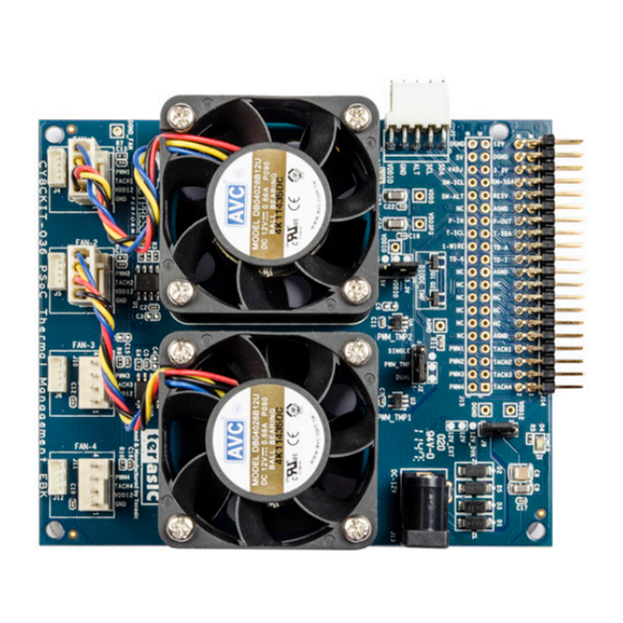
Fan Socket
Temperature
Sensor with
I
C Interface
2
Temperature
Sensor with
One-wire Interface
Temperature Sensor
with a PWM Output
Jumper
Default Setting
SINGLE
J2
PWM_TMP
DUAL
J3
J9
Note:
This Kit is designed to work with the following PSoC
PSoC Development Kit: CY8CKIT-001
PSoC 3 Development Kit: CY8CKIT-030
If you are using a PSoC 4 Pioneer Kit (CY8CKIT-042), you will require a PSoC Adapter Shield Kit (CY8CKIT-019) to
connect the Thermal Management Kit (CY8CKIT-036)
Please ensure the following settings in CY8CKIT-019:
1) Jumpers: Ensure the settings of J5, J6, J7 are compatible
with CY8CKIT-036, as shown in the image
QUICK START GUIDE
I
C Connector
2
Diode
Temperature Sensors
Description
3-pin header to choose between a single-sensor or a dual-sensor (daisy-chain)
connection for the PWM temperature sensors. Place jumper in 1-2 position
to enable dual-sensor daisy-chain mode
3-pin header to set logic signal levels for digital temperature sensors.
Place in 2-3 position for 3.3-V interfacing (and the kit projects)
3-pin header for fan power supply. Place in 1-2 position to source
external power from the power jack (J13)
Development Kits:
®
PSoC 5LP Development Kit: CY8CKIT-050
PSoC 4 Pioneer Kit: CY8CKIT-042
2) Connect a wire from pin 10 of header J9 to pin 1 of header J2
(this is to connect the potentiometer input)
1
2
Kit Contents:
1) Thermal Management Board
2) Power DC Adaptor 12 V/2 A
3) Quick Start Guide
3
QUICK START GUIDE
CY8CKIT-036 THERMAL MANAGEMENT KIT
I
2
C Connector
1
2
2
Fan Socket
Temperature
Sensor with
2
I
C interface
Temperature
Kit Contents:
Sensor with
One-wire interface
1) Thermal Management board
2) Power DC Adaptor 12V/2A
3) Quick Start Guide
Temperature Sensor
Diode
with a PWM output
Temperature Sensors
JUMPER
DEFAULT SETTING
DESCRIPTION
SINGLE
3-pin header to choose between single sensor or dual sensor (daisy-chain)
J2
PWM_TMP
connection for the PWM temperature sensors. Place jumper in 1-2 position
to enable dual sensor daisy-chain moder 3.2
DUAL
3-pin header to set logic signal levels for digital temperature sensors.
J3
Place in 1-2 for 5V interfacing. Place in 2-3 position for 3.3V interfacing
3-pin header for fan power supply. Place in 1-2 position to source external
J9
power from the power jack (J13). Place in 2-3 position to source 12V
power from your PSoC development kit
Note:
This Kit is designed to work with a PSoC Development Kit like:
PSoC Development Kit: CY8CKIT-001
PSoC 3 Development Kit: CY8CKIT-030
PSoC 5LP Development Kit: CY8CKIT-050
PSoC 4 Pioneer Kit: CY8CKIT-042
If you are using a PSoC 4 Pioneer Kit (CY8CKIT-042), you will require a PSoC Adapter Shield Kit (CY8CKIT-019) to
connect the Thermal Management Kit (CY8CKIT-036).
Please ensure the following settings in CY8CKIT-019:
1) Jumper: Ensure the settings of J5, J6, J7 is compatible to work
with CY8CKIT-036 as shown in the image below
2) Connect a wire from pin 10 of header J9 to pin 1 of header J2
(this is for connecting the potentiometer input)
Advertisement
Table of Contents

Related Manuals for Cypress Semiconductor CY8CKIT-036


Summary of Contents for Cypress Semiconductor CY8CKIT-036
- Page 1 C Interface 1) Jumper: Ensure the settings of J5, J6, J7 is compatible to work with CY8CKIT-036 as shown in the image below 2) Connect a wire from pin 10 of header J9 to pin 1 of header J2 (this is for connecting the potentiometer input)
- Page 2 • Download and Install the latest kit software and • Connect your Cypress Programmer examples from www.cypress.com/go/CY8CKIT-036 - If you are using a CY8CKIT-001, connect the MiniProg3 to the PSoC processor module. - If you are using a CY8CKIT-030 (PSoC 3) or...
- Page 3 CY8CKIT-030 or CY8CKIT-001 CY8CKIT-050 CY8CKIT-050 • Connect J14 of the CY8CKIT-036 to: • View the output in the display showing the temperature reading and the fan speed - Port A of CY8CKIT-001 • Use SW1 (in CY8CKIT-001) or SW2 (in CY8CKIT-030/...
- Page 4 • Connect the 12-V/2-A power adapter to the power to learn more about the projects, the thermal algorithms, jack J13 of the Thermal Management Kit (CY8CKIT-036) and the kit For the latest information about this kit and to download kit software and hardware files, visit http://www.cypress.com/go/CY8CKIT-036...
Need help?
Do you have a question about the CY8CKIT-036 and is the answer not in the manual?
Questions and answers