NEC EXP805 User Manual
Hide thumbs
Also See for EXP805:
- Maintenance manual (136 pages) ,
- User manual (262 pages) ,
- Maintenance manual (138 pages)
Table of Contents
Advertisement
Quick Links
Advertisement
Table of Contents

Subscribe to Our Youtube Channel
Related Manuals for NEC EXP805


Summary of Contents for NEC EXP805
- Page 1 User’s Guide NEC Express Server Express5800 Series Express5800/R120h-2M (2nd-Gen) EXP805 (N8100-2775F/2776F/2777F/2778F) Chapter 1 General Description Chapter 2 Preparations Chapter 3 Setup Chapter 4 Appendix 10.201.02-101.01 May 2019 © NEC Corporation 2019...
-
Page 2: Manuals
Getting Started Describes how to use this server, from unpacking to operations. See this guide first and read the outline of this product. The electronic edition has been published on a website (http://www.nec.com/ express/). User’s Guide Chapter 1: General Description Overviews, names, and functions of the server’s parts... -
Page 3: Table Of Contents
Contents Contents Manuals................................. 2 Contents ................................3 Conventions Used in This Document ........................7 Signs and symbols for safety ......................7 Notations used in the text ........................8 Optical disk drive ..........................8 Hard disk drive ............................ 8 Abbreviations of Operating Systems (Windows) ................. 8 Abbreviations of Operating Systems (Linux) .................. - Page 4 Contents Chapter 2 Preparations ............................ 50 1. Installing Internal Optional Devices ........................ 51 1.1 Safety Precautions ........................51 1.2 Overview of Installation and Removal ..................52 1.3 Identifying Servers (UID Switch) ....................54 1.4 Removing Front Bezel ....................... 55 1.5 Removing Top Cover ......................... 56 1.6 Removing the Air Baffle ......................
- Page 5 Contents Removal ......................127 1.20 Flash Backup Unit N8103-218 ....................128 Handling precautions ..................128 Installing Flash Backup Unit (N8103-218) ............128 Removal ......................131 1.21 VMware ESXi USB flash memory for installation (N8106-016/017) ........132 Installation of USB flash memory N8106-016/017 ..........132 Removal ......................
- Page 6 Contents Installing the cable management arm ..............221 Removing the cable management arm ..............223 Chapter 3 Setup ............................. 224 1. Turning on the Server ........................... 225 1.1 POST ............................227 POST sequence ....................227 POST error messages ..................228 2.
-
Page 7: Conventions Used In This Document
Conventions Used in This Document Conventions Used in This Document Signs and symbols for safety WARNING and CAUTION are used in this guide as the following meaning. WARNING Indicates there is a risk of death or serious personal injury CAUTION Indicates there is a risk of burns, other personal injury, or property damage Precautions and notices against hazards are presented with one of the following three symbols. -
Page 8: Notations Used In The Text
Conventions Used in This Document Notations used in the text In addition to safety-related symbols urging caution, three other types of notations are used in this document. These notations have the following meanings. Important Indicates critical items that must be followed when handling hardware or operating software. If the procedures described are not followed, hardware failure, data loss, and other serious malfunctions could occur. -
Page 9: Abbreviations Of Operating Systems (Linux)
Conventions Used in This Document Abbreviations of Operating Systems (Linux) Linux Operating Systems are referred to as follows. Notations in this document Official names of Linux Red Hat Enterprise Linux 7 Server Red Hat Enterprise Linux 7 Server (x86_64) Abbreviations of Operating Systems (VMware) VMware Operating Systems are referred to as follows. -
Page 10: Trademarks
Trademarks Trademarks ExpressUpdate is a registered trademark of NEC Corporation. Microsoft, Windows, and Windows Server are registered trademarks or trademarks of Microsoft Corporation in the United States and other countries. Intel and Xeon are registered trademarks of Intel Corporation of the United States. -
Page 11: License Notification
License Notification License Notification Open source software of following license is included in the part of this product (system utility). UEFI EDK2 License The MIT License Agreement PNG Graphics File Format Software End User License Agreement zlib End User License Agreement UEFI EDK2 License UEFI EDK2 Open Source License... - Page 12 License Notification THIS SOFTWARE IS PROVIDED BY THE COPYRIGHT HOLDERS AND CONTRIBUTORS "AS IS" AND ANY EXPRESS OR IMPLIED WARRANTIES, INCLUDING, BUT NOT LIMITED TO, THE IMPLIED WARRANTIES OF MERCHANTABILITY AND FITNESS FOR A PARTICULAR PURPOSE ARE DISCLAIMED. IN NO EVENT SHALL THE COPYRIGHT OWNER OR CONTRIBUTORS BE LIABLE FOR ANY DIRECT, INDIRECT, INCIDENTAL, SPECIAL, EXEMPLARY, OR CONSEQUENTIAL DAMAGES (INCLUDING, BUT NOT LIMITED TO, PROCUREMENT OF SUBSTITUTE GOODS OR SERVICES;...
- Page 13 License Notification PNG Graphics File Format Software End User License Agreement --------------------------------------------------------------------------- Copyright (c) 1998-2001 Greg Roelofs. All rights reserved. This software is provided "as is," without warranty of any kind, express or implied. In no event shall the author or contributors be held liable for any damages arising in any way from the use of this software.
-
Page 14: Warnings And Additions To This Document
If you have any concerns, or discover errors or omissions in this document, contact your sales representative. Regardless of article 4, NEC Corporation assumes no responsibility for effects resulting from your operations. The sample values used in this document are not actual values. -
Page 15: Warning Label
Warnings and Additions to This Document Warning label Warning label are attached on or near the components with potential hazards. This label is either attached or printed on the component. Do not remove or black out this label and keep it clean. If no label is attached or printed on the server, contact your sales representative. -
Page 16: Handling Precautions (For Proper Operations)
Tape media: Approximately 1 day For optional devices, we recommend you use our NEC products. Even if they are successfully installed or connected, installation of unsupported devices can cause the server to malfunction or even failure. You will be charged to repair failure or damage caused by use of such products even within warranty period. - Page 17 Warnings and Additions to This Document Tips for your health and safety Using a computer extensively may affect different parts of your body. Here are tips you should follow while working on a computer to minimize strain on your body. Keep proper posture The basic body position for using a computer is sitting straight with your hands on the keyboard parallel with the floor, and your eyes...
-
Page 18: Chapter 1 General Description
NEC Express5800 Series Express5800/R120h-2M General Description This chapter introduces the features of this server and the name of each part 1. Introduction 2. Accessories Describes the accessories of the server. 3. Features Describes the features of the server and the server management. -
Page 19: Introduction
Chapter 1 General Description 1. Introduction Introduction Thank you for purchasing this NEC Express5800 Series product. This server is powered by the latest microprocessor "Intel Xeon processor". ® ® With our latest technology and architecture, we offer "high performance" and "high reliability" that could not be accomplished by conventional servers. -
Page 20: Accessories
Chapter 1 General Description 2. Accessories Accessories The carton box contains various accessories which are required for setup or maintenance. Make sure you have them all for future use. The rack or server chassis includes all rack-mounting hardware parts required for the server installation. ... -
Page 21: Features
Chapter 1 General Description 3. Features Features The server has the following features. High performance ® Xeon ® Processor Scalable Family ・Intel Xeon Bronze 3204 Processor (1.90 GHz, 6C/6T, TDP 85W, DDR4 2133 1TB), Xeon Silver 4208 Processor (2.10 GHz, 8C/16T, TDP 85W, DDR4 2400 1TB), Xeon Silver 4210 Processor (2.20 GHz, 10C/20T, TDP 85W, DDR4 2400 1TB), Xeon Silver 4214 Processor (2.20 GHz, 12C/24T, TDP 85W, DDR4 2400 1TB), Xeon Silver 4215 Processor (2.50 GHz, 8C/16T, TDP 85W, DDR4 2400 1TB),... - Page 22 ・The security lock that comes with Front Bezel ・Redundant fan configuration ・Fan (hot swapping supported) ・HDD (hot swapping supported) Management Utilities ・NEC ESMPRO ・Remote controlling feature (iLO5) ・RAID system management utility (Smart Storage Administrator) ・Hard disk drive monitoring ・Power supply monitoring Power saving and noiseless design Express5800/R120h-2M (2nd-Gen) User’s Guide...
- Page 23 Chapter 1 General Description 3. Features ・Selection of power unit appropriate to environment, work load, and configuration ・Power consumption monitoring feature ・Power control feature ・80 PLUS ® Platinum / Titanium certified high efficiency power supply *6 ・Fan control appropriate to environment, work load, and configuration ・Silent sound design ®...
- Page 24 Chapter 1 General Description 3. Features Easy setup ・EXPRESSBUILDER (setup utility) ・System utility *1: The Intel Xeon processor Bronze 3200 series is not supported. *2: The device that mounts Intel Xeon processor Bronze 3200 series/Silver 4200 series/Gold 5200 series executes one instruction simultaneously. The device that mounts Gold 6200 series/Platinum 8200 series executes two instructions simultaneously.
-
Page 25: Names And Functions Of Parts
Chapter 1 General Description 4. Names and Functions of Parts Names and Functions of Parts This section describes the names of the server parts. Front View (With Front Bezel) (1) Front Bezel (2) Key Slot A cover for protecting the front of the server. This A slot for Bezel Lock Key that is used to lock Front cover can be locked with the provided Bezel Lock Bezel. -
Page 26: Front View (Without Front Bezel)
Chapter 1 General Description 4. Names and Functions of Parts Front View (Without Front Bezel) ・8 x 2.5-inch drive model (2)-1 (2)-3 (2)-5 (2)-7 (2)-2 (2)-4 (2)-6 (2)-8 ・Universal media bay (11) (13) (14) (14) (10) ・24 x 2.5-inch drive model (2)-1 (2)-5 (2)-9... - Page 27 Chapter 1 General Description 4. Names and Functions of Parts ・12 x 3.5-inch drive model (12)-1 (12)-2 (12)-3 (12)-4 (12)-1 (12)-2 (12)-3 (12)-4 (12)-3 (12)-2 (12)-1 (12)-4 (1) Expansion Bay (8) USB3.0 connector (front) Used for installing the optional hard disk drive, Connectors for connecting USB 3.0 interface universal media bay devices.
-
Page 28: Rear View
Chapter 1 General Description 4. Names and Functions of Parts Rear View (13) (14) (4)-1 (5)-4 (4)-2 (6)-8 (6)-7 (5)-5 (5)-6 (4)-3 (11) (16) (15) (11) (12) (10)-1 (10)-2 (10)-3 (10)-4 Power Unit (Power supply slot 1) (10) LAN connectors (Required option) A power supply for supplying Connectors for connecting to a network... -
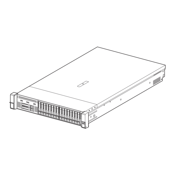
Page 29: External View
Chapter 1 General Description 4. Names and Functions of Parts External View (1) Top cover (2) Hood latch Express5800/R120h-2M (2nd-Gen) User’s Guide... -
Page 30: Internal View
Chapter 1 General Description 4. Names and Functions of Parts Internal View The diagram omits the air duct. (3)-2 (2)-2 (2)-1 (10)-1 (2)-3 (11) (10)-2 (2)-4 (2)-5 (2)-6 (3)-1 (1) Backplane (7) Primary Riser Card Standard riser is standard-installed (2) Cooling Fan Changeable by option -1 FAN1 (option) -2 FAN2 (option) -
Page 31: Motherboard
Chapter 1 General Description 4. Names and Functions of Parts Motherboard (23) (22) (21) (20) (17) (19) (15) (18) (16) (10) (11) (14) (12) (1)-1 (1)-2 (24) (24) (24) (13) Processor (CPU) Socket (12) Power supply SW/USB 3.0 connector -1 Processor #1 (CPU #1) (13) Battery connector for RAID controller -2 Processor #2 (CPU #2) (14) Power Connector for Expander Board... -
Page 32: System Maintenance Switch
Chapter 1 General Description 4. Names and Functions of Parts System Maintenance Switch Position Default Setting Description SW1 *1,*5 Off Set to OFF at regular times. Sets the security of iLO5 to disabled. Reserved Reserved Reserved SW5 *2,*5 Off Set to OFF at regular times. Clear power-on password and administrator password. -
Page 33: Cooling Fan Option
Chapter 1 General Description 4. Names and Functions of Parts Cooling Fan Option Important To prevent damage to server components, make sure to install fan covers on fan bays 1 and 2 for single processor configurations. Important To prevent damage to the device, do not let the server operate for extended lengths of time without the appropriate number of fans installed. - Page 34 Configuration (RBSU),” Server Component may be damaged by a high temperature event. Tips In case NEC ESMPRO ServerAgentService is installed, since a shut down due to high temperature is executed by NEC ESMPRO ServerAgentService, you need to set “Thermal Shutdown” to “Disabled.”...
-
Page 35: Status Indicators
Chapter 1 General Description 4. Names and Functions of Parts Status Indicators LEDs on the front side of the unit ・2.5-inch drive model Item Status Description Power switch and system Lights in green The system is powered on power LED Flashes in green (once per The power on sequence in progress second) - Page 36 Chapter 1 General Description 4. Names and Functions of Parts ・12x3.5-inch drive model Item Status Description STATUS LED Lights in green Normal state Flashes in green (once per Restarting iLO second) Flashes in amber The function of the system is deteriorating Flashes in red (once per The system is in a critical state second)
- Page 37 Chapter 1 General Description 4. Names and Functions of Parts ・8x3.5-inch drive model Item Status Description UID switch/LED Lights in blue Working in operation ※Do not reboot the iLO from Flashes in blue (once per Remote management or firmware upgrade is the boot of the server until second) in progress...
- Page 38 Chapter 1 General Description 4. Names and Functions of Parts (1) UID switch function To display Server Health Summary, press the UID switch. To restart iLO, press and hold the UID switch until the UID lamp starts blinking fast in blue (4 times per second). Do not restart iLO during the time from when the server starts up Important until the OS startup is completed (including the execution of POST...
- Page 39 Chapter 1 General Description 4. Names and Functions of Parts Item Status Description Processor LED Lights off Normal state Amber Processor has failed DIMM LED Lights off Normal state Amber The DIMM has failed or there is a configuration problem Cooling fan LED Lights off Normal state...
- Page 40 Chapter 1 General Description 4. Names and Functions of Parts (4) Status LED Panel combined LED descriptions The combined illumination of the following LEDs indicates a system condition: • Systems Insight Display LEDs • System power LED • Health LED Status LED Panel Status System...
-
Page 41: Leds On The Backside Of The Unit
Chapter 1 General Description 4. Names and Functions of Parts LEDs on the backside of the unit Item Status Description UID LED Lights in blue Confirmation function is used. Flashes in blue The system is remotely managed. Lights off Confirmation function is not used. LINK LED Lights in green Connected. -
Page 42: Hot Plug Compatible Sata/Sas Drive Led
Chapter 1 General Description 4. Names and Functions of Parts Hot plug compatible SATA/SAS drive LED Item Status Description Position Check LED Lights in blue The drive is identified by the host application Flashes in blue Firmware on the drive carrier is being updated or requires updating DISK ACT LED Rotates in green... -
Page 43: Optical Disk Drive Access Led (Optional)
Chapter 1 General Description 4. Names and Functions of Parts Optical Disk Drive Access LED (optional) The LED for optical disk drive at the front of the server flashes when a CD or DVD is being accessed. The access LED of optical disk drive Express5800/R120h-2M (2nd-Gen) User’s Guide... -
Page 44: Identification Of Drive Boxes
Chapter 1 General Description 4. Names and Functions of Parts Identification of Drive Boxes Front BOX Chart number BOX number BOX1 BOX2 BOX3 Chart number BOX number BOX1 BOX2 BOX3 Rear BOX Chart number BOX number BOX4 BOX5 BOX6 Express5800/R120h-2M (2nd-Gen) User’s Guide... -
Page 45: Mid Box
Chapter 1 General Description 4. Names and Functions of Parts Chart number BOX number BOX4 BOX6 Mid BOX Chart number BOX number BOX7 Express5800/R120h-2M (2nd-Gen) User’s Guide... -
Page 46: Device Number
Chapter 1 General Description 4. Names and Functions of Parts 4.10 Device Number Drive bay numbers may differ according to the connection of a drive back plane and a controller. Controller Connection to a on-board SATA port ‑ Connection to a PCI board (AROC Type-a) to be installed on a dedicated connector for RAID ‑... - Page 47 Chapter 1 General Description 4. Names and Functions of Parts Front Express5800/R120h-2M (2nd-Gen) User’s Guide...
-
Page 48: Drive Bay Numbers When Sas Expander Is Used
Chapter 1 General Description 4. Names and Functions of Parts Drive bay numbers when SAS expander is used If you connect via an SAS Expander, the drive bay numbers become sequential. ・SAS Expander Port 1 is always connected to Port 1 of RAID Controller. ・SAS Expander Port 2 is always connected to Port 2 of RAID Controller. - Page 49 Chapter 1 General Description 4. Names and Functions of Parts In the case of 12x 3.5 inch drive + middle 4x 3.5 inch drive + rear 2x2.5 inch drive cages x3 Rear 2.5-inch Rear 3.5-inch Express5800/R120h-2M (2nd-Gen) User’s Guide...
-
Page 50: Chapter 2 Preparations
NEC Express5800 Series Express5800/R120h-2M Preparations This chapter describes preparations for using this server. 1. Installing Internal Optional Devices You can skip this section if you did not purchase any optional devices. 2. Installation and Connection Place the server in a suitable location and connect cables following this section. -
Page 51: Installing Internal Optional Devices
This section describes the instructions for installing supported optional devices and precautions. Important Use only the devices and cables specified by NEC. You will be charged to repair damages, malfunctions, and failures caused by the use of any devices or cables not specified for use with this server even within the warranty period. -
Page 52: Overview Of Installation And Removal
Chapter 2 Preparations 1. Installing Internal Optional Devices Overview of Installation and Removal Install/remove components by using the following procedure. Installing or removing internal parts such as hard disk drives, fan units, and power units is done while the rack is removed from the server. - Page 53 Chapter 2 Preparations 1. Installing Internal Optional Devices Remove the air baffle. See Chapter 2 (1.6 Removing the Air Baffle). Depending on the components to be installed or removed, follow the procedure in order. See Chapter 2 (1.7 TPM Kit N8115-35) to (1.32 Use of Internal Hard Disk Drives in the RAID System).
-
Page 54: Identifying Servers (Uid Switch)
Chapter 2 Preparations 1. Installing Internal Optional Devices Identifying Servers (UID Switch) Using UID (Unit ID) Switch helps you to identify the target server. When the server is working, be sure to identify the target server by using UID Switch first before you turn off the server or disconnect a cable from the server. -
Page 55: Removing Front Bezel
Chapter 2 Preparations 1. Installing Internal Optional Devices Removing Front Bezel Remove the front bezel when pressing the POWER switch or removing Top Cover. To unlock the bezel, insert the attached Bezel Lock Key into the key slot and turn the key. Unlock Lock Press to the right and unlock the lever seen on the left when you face the front bezel, and pull only... -
Page 56: Removing Top Cover
Chapter 2 Preparations 1. Installing Internal Optional Devices Removing Top Cover Remove Top Cover when installing or removing the optional component or change internal cable connection. Please have ready a hexalobular driver (T-10) or flathead driver. See steps 1 to 5 in Chapter 2 (1.2 Overview of Installation and Removal) for preparations. Unscrew the security screw with the hexalobular driver or flathead driver. -
Page 57: Removing The Air Baffle
Chapter 2 Preparations 1. Installing Internal Optional Devices Removing the Air Baffle Note Do not remove the cable connecting the cache module from Flash Backup Unit pack. If the cable is disconnected, the data stored in the cache module will be lost. Note Do not let the server operate for extended lengths of time with the top cover, air baffle, expansion slot cover, or the blank cover removed. -
Page 58: Tpm Kit N8115-35
Chapter 2 Preparations 1. Installing Internal Optional Devices TPM Kit N8115-35 Overview Install the TPM (Trusted Platform Module) Kit unit according to the instructions in this section to enable it. There are two steps to follow. 1. Installation of TPM Kit 2. -
Page 59: Installing The N8115-35 Tpm Kit
Chapter 2 Preparations 1. Installing Internal Optional Devices Check the position of the TPM installer connector on the figure below. TPM KIT CONNECTORS Installing the N8115-35 TPM Kit Procedure Important To reduce the risk of personal injury, electric shock, or damage to the equipment, remove power from the server by removing the power cord. - Page 60 Chapter 2 Preparations 1. Installing Internal Optional Devices Match the TPM kit with the connector grooves on the motherboard. Press the connector in firmly and install the TPM kit. Please check the location of the TPM connector on the motherboard by looking at the quick reference level attached to the back of the top cover.
-
Page 61: Enable Tpm
If you need detailed information on the update of firmware and the procedure of hardware, refer to the Web Site of NEC Support Center. For details on how to adjust the TPM Kit used for BitLocker, visit the Microsoft website. -
Page 62: Processor (Cpu)
Important Safety Precautions and Regulatory Notices. Make sure to use the CPU authorized by NEC. Installing a third-party CPU may cause a failure of the CPU as well as the motherboard. Repair of the server due to failures or damage resulted from installing such a CPU will be charged. -
Page 63: Maximum Number Of Processor Cores Supported By This Server
Chapter 2 Preparations 1. Installing Internal Optional Devices Maximum number of processor cores supported by this server The maximum number of processor cores (logical processors) available on the server depends on the architecture (x86 architecture) and OS specs. The maximum number of The maximum number of logical processors logical processors supported... - Page 64 Chapter 2 Preparations 1. Installing Internal Optional Devices Note Be sure to tighten each heatsink nut fully in the order indicated. Otherwise, boot failure or intermittent shutdowns might occur.Do not touch the point of contact of the processor. Using a T-30 Hexalobular screwdriver, fully tighten each heatsink nut in the order indicated on the ③...
- Page 65 Chapter 2 Preparations 1. Installing Internal Optional Devices Install an additional fan unit provided with additional CPU kit. Remove the fan blank cover from the fan bay. Attach the fan to bay 1 and 2. Fan connection conditions are shown in the table below. Fan bay Configuration 1xCPU...
-
Page 66: Identifying Processor Type
Chapter 2 Preparations 1. Installing Internal Optional Devices See Chapter 2 (1.33 Attaching the air baffle) to attach the air baffle. See Chapter 2 (1.34 Installing Top Cover) to attach the top cover of the server. Note In order to prevent damage of the system due to improper cooling or elevated temperature, please do not activate the server or enclosure without implementing any of component or blank on all of drive bays and device bays. -
Page 67: High-Performance Fan N8181-158
Chapter 2 Preparations 1. Installing Internal Optional Devices High-performance fan N8181-158 Installing N8181-158 High-performance fan Note To prevent damage to the server, confirm that all DIMM latches are locked before installing the fans. Note Do not let the server operate for extended lengths of time with the top cover open or removed. -
Page 68: Removal
Chapter 2 Preparations 1. Installing Internal Optional Devices Remove all standard fans from the fan bays. Important Do not mix standard and high-performance fans in the same server. Install all high-performance fans to the fan bay. See Chapter 2 (1.33 Attaching the air baffle) to attach the air baffle. See Chapter 2 (1.34 Installing Top Cover) to attach the top cover of the server. -
Page 69: Hot-Pluggable Fan
If the shutdown function due to high temperature is disabled in system utility, equipment parts may become damaged by high temperatures. Tips In case NEC ESMPRO ServerAgentService is installed, since a shut down due to high temperature is executed by NEC ESMPRO ServerAgentService, you need to set “Thermal Shutdown” to “Disabled.”... -
Page 70: High-Performance Cpu Heat Sink Module N8101-1286, 1U Heat Sink
Chapter 2 Preparations 1. Installing Internal Optional Devices 1.10 High-performance CPU heat sink module N8101-1286, 1U heat sink This procedure is illustrated with a standard heat sink as the example. The install method is same for all heat sinks. Before installing, check the parts of processor, heat sink, and plug. Handling precautions To prevent personal injury, electrical shock or equipment damage, unplug the power cord and ensure no power is supplied to the server. - Page 71 Chapter 2 Preparations 1. Installing Internal Optional Devices In case a 4x3.5-inch drive of mid plane is installed, remove it. Remove the processor heat sink module. Wait for the heat sink to cool. Use a hexalobular driver to loosen the heat sink screws (4 PCs) in the following order (1→2→3→4). Note Contacts on the motherboard are very fragile and easily damaged.
- Page 72 Chapter 2 Preparations 1. Installing Internal Optional Devices Insert a 1/4-inch wide flat-blade screwdriver into the release slot. Note To avoid damage to the processor, insert the tool between the processor and the heatsink base. The opening in the carrier provides access to a gap between the processor heatsink spreader and the heatsink base.
- Page 73 Chapter 2 Preparations 1. Installing Internal Optional Devices Confirm the location of the processor, remove the processor socket protective cover. Note Keep the removed protective cover for future use. 10. Install the processor heatsink assembly: ① Locate the Pin 1 indicator on the processor carrier and the socket. ②...
-
Page 74: Identifying Processor Type
Chapter 2 Preparations 1. Installing Internal Optional Devices 11. Make sure that the heat sink is installed on a level with the motherboard. If the heat sink is not level, remove it, and then install it again.The following Note probably causes the heat sink not to be level: –... -
Page 75: Dimm
Chapter 2 Preparations 1. Installing Internal Optional Devices 1.11 DIMM Install a Dual Inline Memory Module (DIMM) to a DIMM slot on the motherboard in the server. The motherboard provides 24 slots to install DIMMs. To avoid static electricity, see Chapter 1 (1.8Anti-static Measures) in Safety Important Precautions and Regulatory Notices. -
Page 76: Dimm Installation Order
Chapter 2 Preparations 1. Installing Internal Optional Devices DIMM installation order Note See Memory RAS features supported by additional memory board in 1.11.3 Memory RAS Feature before using memory RAS feature. This server's memory subsystem is divided into channels. Each processor supports 6 channels and each channel supports 2 DIMM slots. - Page 77 Chapter 2 Preparations 1. Installing Internal Optional Devices When CPU1 and CPU2 are mounted DIMM slot CPU2 CPU1 number 9 10 11 12 9 10 11 12 2 DIMM 3 DIMM 4 DIMM 5 DIMM 6 DIMM 7 DIMM 8 DIMM 9 DIMM 10 DIMM 11 DIMM...
-
Page 78: Memory Processor Compatibility Information
Chapter 2 Preparations 1. Installing Internal Optional Devices Memory processor compatibility information Memory clock frequency Operating frequency of DDR4 memory varies by processor type and memory configuration. Please refer to the table below for the actual maximum operating frequency. Operating frequency driving CPU brand voltage 1.2 V... -
Page 79: Checking Dimm
Chapter 2 Preparations 1. Installing Internal Optional Devices Checking DIMM To check out the features of the DIMM, please refer to the label affixed to the DIMM, the following illustrations and tables. Number Description Meaning 16GB 32GB Capacity 64GB 128GB 1R = Single rank 2R = Dual rank Rank... -
Page 80: Installation
Chapter 2 Preparations 1. Installing Internal Optional Devices Installation Follow the steps below to install a DIMM. See steps 1 to 7 in Chapter 2 (1.2 Overview of Installation and Removal) for preparations. For the 3.5-inch drive model, if the mid-plane drive cage is attached, it must be removed. Open levers on left and right sides of DIMM slot. -
Page 81: Removal / Replacement
Note When removing a defective DIMM, check error messages displayed at POST or NEC ESMPRO and check the DIMM socket where the defective DIMM is installed. Please check if there is no error on POST after replacing/removing DIMM. Express5800/R120h-2M (2nd-Gen) User’s Guide... -
Page 82: Memory Functions
Chapter 2 Preparations 1. Installing Internal Optional Devices Memory functions This server is equipped with the "Advanced ECC function", "Memory ADDDC function", "Memory Mirroring function", and "Memory Sparing function" as memory RAS functions. The "Advanced ECC function" corrects memory errors to continue operation when errors occur on the same DRAM device on the DIMM. - Page 83 Chapter 2 Preparations 1. Installing Internal Optional Devices PROC1 Memory Controller 1 Memory Controller 2 PROC2 Memory Controller 1 Memory Controller 2 Express5800/R120h-2M (2nd-Gen) User’s Guide...
- Page 84 Chapter 2 Preparations 1. Installing Internal Optional Devices (1) Memory Mirroring Function Memory Mirroring Function is a function to generate redundancy by writing the same data into DIMM group (mirror set) composed of three channels under the same memory controller (channel1, channel 2 and channel 3 or channel 4, channel 5 and channel 6).
- Page 85 Chapter 2 Preparations 1. Installing Internal Optional Devices The following mirroring cannot be configured. ● Memory mirroring in the same memory channel When using Memory Mirroring Function, install 12 DIMMs per CPU. Note Use memories with the same product number for the device. ...
- Page 86 Chapter 2 Preparations 1. Installing Internal Optional Devices (2) Memory Sparing Function By making a rank of DIMM stored in the memory channel under a memory controller of each CPU stand by as a spare, Memory Sparing Function makes processing continue by making the DIMM standing by perform the task automatically in case a correctable error occurs in a DIMM under the memory channel in operation.
- Page 87 Chapter 2 Preparations 1. Installing Internal Optional Devices Mount DIMMs in the DIMM slot constituting a spare set. ● Change the following parameters and save them. ● From System Utility, set "System Configuration > BIOS/Platform Configuration (RBSU) > Memory Oprations > Advanced Memory Protection" to "Online Spare with Advanced ECC Support". After rebooting, confirm "Advanced Memory Protection Mode:Online Spare with Advanced ●...
- Page 88 Chapter 2 Preparations 1. Installing Internal Optional Devices (3) Fault tolerant memory function (ADDDC) In case of failures in two chips of more than one memory and chip that are mounted in DIMM, the fault tolerant function (ADDDC) automatically recovers the data and enables the system to continuously run. Tips Mount DIMM according to 1.10.2 Procedure for adding DIMM.
-
Page 89: Riser Card
Chapter 2 Preparations 1. Installing Internal Optional Devices 1.12 Riser Card The device is a highly expandable one equipped with “Primary Riser Card” to which 3 PCI boards (Slot 1/2/3) can be fit, “Secondary Riser Card” to which 3 PCI boards (Slot 4/5/6) can be fit and “Tertiary Riser Card (Butterfly Riser)”... - Page 90 Chapter 2 Preparations 1. Installing Internal Optional Devices Raise the screw handles located on the upper part of the riser card and turn it 180° to the left. Then, pull the riser card up to remove it. Adjust the position of the riser card edge of the riser card to the position of the connector, and push it in place from above.
-
Page 91: Installing Secondary Riser Card
Chapter 2 Preparations 1. Installing Internal Optional Devices Installing Secondary Riser Card Please prepare the following before installing the options. Parts included in the option kit T-10 hexalobular driver Note In order to prevent the damage to server's main body or the expansion board, please remove all the AC power cables before removing/installing riser card. -
Page 92: Installing Tertiary Riser Card
Chapter 2 Preparations 1. Installing Internal Optional Devices See Chapter 2 (1.33 Attaching the air baffle) to attach the top cover of the server. Note In order to prevent damage of the system due to improper cooling or elevated temperature, please do not activate the server or enclosure without implementing any of component or blank on all of drive bays and device bays. - Page 93 Chapter 2 Preparations 1. Installing Internal Optional Devices Unfasten 3 screws and remove secondary riser card. Attach the secondary riser card removed in step 3 to secondary side of tertiary riser card (butterfly riser card), and fasten with 3 screws. After that, proceed to step 6. Remove the 2 screws that fix the secondary riser blank cover in place, and remove the cover by lifting it up.
- Page 94 Chapter 2 Preparations 1. Installing Internal Optional Devices Remove the 3 screws that fix the tertiary riser blank cover in place, and remove the cover by lifting it up. Note Keep each removed blank covers. Take out a rear blank from the option kit, fit the blank cover from the upper direction and fix it with two screws.
-
Page 95: Removal
Chapter 2 Preparations 1. Installing Internal Optional Devices Adjust the position of the riser card edge of the tertiary riser card to the position of the connector, and push it in place from above. Raise the 2 screw handles located on the upper part of the riser card and push it downwards while turning it 180°... -
Page 96: M.2 Sata Ssd
Chapter 2 Preparations 1. Installing Internal Optional Devices 1.13 M.2 SATA SSD Installing M.2 SATA SSD media Note In order to prevent the damage to electronic components, please start to install the system after conducting the appropriate anti-static treatment. There is a possibility of causing electrostatic discharge if appropriate grounding wire treatment is not conducted. -
Page 97: Removal
Chapter 2 Preparations 1. Installing Internal Optional Devices Insert the edge of M.2 SSD media to connector, take down the media to the stud attached in step 3, and then fix with a screw. Fit the riser card edge of primary riser card to the position of connector and push the edge into the connector from above. -
Page 98: Pci Board
Chapter 2 Preparations 1. Installing Internal Optional Devices 1.14 PCI board The device is equipped with “Riser Cards (3 types)” to which a PCI board can be fit, “LOM Card dedicated Slot” to which an LOM Card can be fit, and “RAID Controller dedicated Slot” to which a RAID controller can be fit. 8 full-height PCI boards can be fit to riser card, one LOM card can be fitted to LOM Card dedicated Slot, and one RAID Controller can be fit to RAID Controller dedicated Slot. -
Page 99: Notes
Chapter 2 Preparations 1. Installing Internal Optional Devices Notes Read the following notes when installing or removing a PCI board. Do not touch the terminals of the PCI board and the leads of electronic components with your bare hand. Fingerprints and dust left on them cause the server to malfunction due to a connection failure or damage to the leads. - Page 100 Chapter 2 Preparations 1. Installing Internal Optional Devices Part number Part name Riser card name RAID LOM 1st riser card *3 2nd riser card *3 3rd riser card*3 Slot number - - SLOT1 SLOT2 SLOT3 SLOT4 SLOT5 SLOT6 SLOT7 SLOT8 CPU connected CPU1 CPU2...
- Page 101 Chapter 2 Preparations 1. Installing Internal Optional Devices (2) Riser Card List 1st riser card (PCIe3.0) SLOT1 SLOT2 SLOT3 Others Slot Slot Slot Part number Slot form Slot form Slot form M.2 SATA GPU power performa Slot size performa Slot size performa Slot size SSD slot...
-
Page 102: Installing Pci Board In The Primary/Secondary Riser
Chapter 2 Preparations 1. Installing Internal Optional Devices Installing PCI board in the primary/secondary riser Read the following notes first. Important When installing a PCI card, make sure the connector of the card fits the connector of the riser card. Note Check the card type which respective riser card supports and the type of PCI card to be installed. - Page 103 Chapter 2 Preparations 1. Installing Internal Optional Devices Open the parts fixing the blank cover of riser card to direction (1) and remove the blank cover by pulling it out to direction (2). Note Keep each removed blank covers. Properly insert the PCI Card port component into the riser card connector, and close it by shutting the PCI card fixing component in the direction of (2).
- Page 104 Chapter 2 Preparations 1. Installing Internal Optional Devices Fit the terminal of riser card to the slot on the mother board and insert the terminal firmly into the slot. Then fix the riser card. Next, raise the screw handle at the top of cage and turn the handle to the right 180 degrees to fix the cage.Then put down the screw handle as before.
-
Page 105: Installing The Tertiary Riser Pci Card
Chapter 2 Preparations 1. Installing Internal Optional Devices Installing the Tertiary Riser PCI Card Read the following notes first. Important When installing a PCI card, make sure the connector of the card fits the connector of the riser card. Note Check the card type which respective riser card supports and the type of PCI card to be installed. -
Page 106: Removal
Chapter 2 Preparations 1. Installing Internal Optional Devices Make sure that the edge of a PCI card bracket is seated into the fixed slot of Note the riser card unit. Depending on type of PCI cards, the terminal part of the PCI card may be too large to fit in the connector. -
Page 107: Raid Controller (Pci Board Type-P)
Chapter 2 Preparations 1. Installing Internal Optional Devices 1.15 RAID controller (PCI Board Type-p) RAID controller (PCI Board) is supported. RAID controller N8103-195/196/201 are provided. Important The surface becomes hot after use so to avoid burns please allow the drive and internal parts of the system to cool before touching. - Page 108 Chapter 2 Preparations 1. Installing Internal Optional Devices Open the parts fixing the blank cover of riser card to direction (1) and remove the blank cover by pulling it out to direction (2). Note Keep each removed blank covers. Fit properly the terminal parts of PCI board to the connector of riser card and insert the terminal parts into the connector.
- Page 109 Chapter 2 Preparations 1. Installing Internal Optional Devices Fit the terminal of riser card to the slot on the mother board and insert the terminal firmly into the slot. Then fix the riser card. Next, raise the screw handle at the top of cage and turn the handle to the right 180 degrees to fix the cage.Then put down the screw handle as before.
-
Page 110: Removal
Chapter 2 Preparations 1. Installing Internal Optional Devices See Chapter 2 (1.33 Attaching the air baffle) to attach the air baffle. 10. See Chapter 2 (1.34 Installing Top Cover) to attach the top cover of the server. Note In order to prevent damage of the system due to improper cooling or elevated temperature, please do not activate the server or enclosure without implementing any of component or blank on all of drive bays and device bays. -
Page 111: Raid Controller N8103-189/190/191 (Aroc Type-A)
Chapter 2 Preparations 1. Installing Internal Optional Devices 1.16 RAID controller N8103-189/190/191 (AROC Type-a) This server supports RAID controller PCI board dedicated slot. RAID controller PCI board dedicated slot Important The surface becomes hot after use so to avoid burns please allow the drive and internal parts of the system to cool before touching. -
Page 112: Removal
Chapter 2 Preparations 1. Installing Internal Optional Devices Position the guide pin of the RAID controller to the connector of the motherboard, firmly insert it from above, tighten the screws securing it in place. Connect Front Disc BP and RAID Controller with SAS Cable. See Chapter 2 (1.33 Attaching the air baffle) to attach the air baffle. -
Page 113: Sas Expander N8116-51
Chapter 2 Preparations 1. Installing Internal Optional Devices 1.17 12G SAS Expander N8116-51 Make sure that the following requirements are met before installing the 12G SAS Expander. You should install the following components. RAID controller Drive cage: ... -
Page 114: Installation
Chapter 2 Preparations 1. Installing Internal Optional Devices Installation Please prepare the following before installing the options. Parts included in the option kit To install the components, follow these steps. See steps 1 to 7 in Chapter 2 (1.2 Overview of Installation and Removal) for preparations. Remove the fan cage. - Page 115 Chapter 2 Preparations 1. Installing Internal Optional Devices Press down the parts fixing the blank cover of riser card and open the cover to direction (2). Then remove the blank cover of Slot 3. Note Keep each removed blank covers. Properly insert the SAS Expander Card port component into the riser card connector, and close it by shutting the PCI card fixing component in the direction of (2).
- Page 116 Chapter 2 Preparations 1. Installing Internal Optional Devices Fit the terminal of riser card to the slot on the mother board and insert the terminal firmly into the slot. Then fix the riser card. Next, raise the screw handle at the top of cage and turn the handle to the right 180 degrees to fix the cage.Then put down the screw handle as before.
- Page 117 Chapter 2 Preparations 1. Installing Internal Optional Devices ・Connecting the PCI board (Type-p) exclusively for the RAID controller and the SAS expander Connect the SAS expander and the backplanes of the various drive cages. ・Connecting the backplane of the 2.5-inch drive BOX 1 and the SAS expander ・Connecting the backplane of the 2.5-inch drive BOX 2 and the SAS expander Express5800/R120h-2M (2nd-Gen) User’s Guide...
- Page 118 Chapter 2 Preparations 1. Installing Internal Optional Devices ・Connecting the backplane of the 2.5-inch drive BOX 1, BOX 2, BOX 3 and the SAS expander ・Connecting the backplane of the rear primary 2.5-inch drive cage and the SAS expander ・Connecting the backplane of the rear secondary 2.5-inch drive cage and the SAS expander Express5800/R120h-2M (2nd-Gen) User’s Guide...
- Page 119 Chapter 2 Preparations 1. Installing Internal Optional Devices ・Connecting the backplane of the rear tertiary 2.5-inch drive cage and the SAS expander ・Connecting the backplane of the rear 3x3.5-inch drive cage and the SAS expander ・Connecting the backplane of the midplane 4x3.5-inch drive cage and the SAS expander Express5800/R120h-2M (2nd-Gen) User’s Guide...
- Page 120 Chapter 2 Preparations 1. Installing Internal Optional Devices Remove all the fans from the fan cage to the state where only the fan cage is left. Next, align the fan cage with the device, push the cage slowly from the above direction, and tilt both sides of the levers to secure it.
-
Page 121: Removal
Chapter 2 Preparations 1. Installing Internal Optional Devices 11. Reinstall all the fans that have been removed earlier. 12. See Chapter 2 (1.33 Attaching the air baffle) to attach the air baffle. 13. See Chapter 2 (1.34 Installing Top Cover) to attach the top cover of the server. Note In order to prevent damage of the system due to improper cooling or elevated temperature, please do not activate the server or enclosure without implementing... -
Page 122: Gpu Card
Chapter 2 Preparations 1. Installing Internal Optional Devices 1.18 GPU Card The GPU card can be installed in each position of the primary, secondary or tertiary slot. The procedure for installing in the secondary slot position is described here. Important You must avoid static electricity to work with the procedure below. - Page 123 Chapter 2 Preparations 1. Installing Internal Optional Devices Attach the appropriate retaining clip parts to the air baffle. The locations of primary, secondary and tertiary are shown in the figure. Attach the clip parts according to each configuration. Install the high performance heat sink. See Chapter 2 (1.10 High-performance CPU heat sink module N8101-1286, 1U heat sink).
- Page 124 Chapter 2 Preparations 1. Installing Internal Optional Devices Align and insert the terminal part of the GPU board correctly into the connector of the riser card, and secure the GPU with screws. Then, close the part in the direction of (3). Connect a power cable from the GPU to a power connector on the riser.
-
Page 125: Removal
Chapter 2 Preparations 1. Installing Internal Optional Devices 12. Slide the retaining clip to the lock side. 13. See Chapter 2 (1.34 Installing Top Cover) to attach the top cover of the server. Note In order to prevent damage of the system due to improper cooling or elevated temperature, please do not activate the server or enclosure without implementing any of component or blank on all of drive bays and device bays. -
Page 126: Lom Card
Chapter 2 Preparations 1. Installing Internal Optional Devices 1.19 LOM Card The server supports LOM Card which is the replaceable onboard network adapter. Install LOM Card to the LOM Card slot on motherboard. The motherboard has one slot to install LOM Card. Important You must avoid static electricity to work with the procedure below. -
Page 127: Removal
Chapter 2 Preparations 1. Installing Internal Optional Devices Align the LOM card pins to the LOM connector of the motherboard and insert it. Tighten the screws firmly. Fit the terminal of riser card to the slot on the mother board and insert the terminal firmly into the slot. Then fix the primary riser card. -
Page 128: Flash Backup Unit N8103-218
Chapter 2 Preparations 1. Installing Internal Optional Devices 1.20 Flash Backup Unit N8103-218 When mounting a RAID controller (N8103-190/191/196/201), by installing Flash Backup Unit, data loss due to accident such as power shortage can be avoided. if Write Back being enabled, Handling precautions When using Flash Backup Unit, please pay attention to the following. - Page 129 Chapter 2 Preparations 1. Installing Internal Optional Devices Remove the fan cage. Install Flash Backup Unit. Connect the cable. Express5800/R120h-2M (2nd-Gen) User’s Guide...
- Page 130 Chapter 2 Preparations 1. Installing Internal Optional Devices Remove all the fans from the fan cage to the state where only the fan cage is left. Next, align the fan cage with the device, push the cage slowly from the above direction, and tilt both sides of the levers to secure it.
-
Page 131: Removal
Chapter 2 Preparations 1. Installing Internal Optional Devices Reinstall all the fans that have been removed earlier. See Chapter 2 (1.33 Attaching the air baffle) to attach the air baffle. 10. See Chapter 2 (1.34 Installing Top Cover) to attach the top cover of the server. Note In order to prevent damage of the system due to improper cooling or elevated temperature, please do not activate the server or enclosure without implementing... -
Page 132: Vmware Esxi Usb Flash Memory For Installation (N8106-016/017)
Chapter 2 Preparations 1. Installing Internal Optional Devices 1.21 VMware ESXi USB flash memory for installation (N8106-016/017) VMware ESXi USB flash memory for installation (N8106-016/017) can be connected to USB 3.0 connector inside the device. Two types of USB flash memory are prepared. ①... -
Page 133: Removal
Chapter 2 Preparations 1. Installing Internal Optional Devices Insert USB flash memory into the connector. Removal When removing, practice the steps of installing reversely. When you operate the device without components, install the blank cover that was installed on the device. Important In order to maintain the cooling effect inside, install the blank cover which you removed. -
Page 134: 8X 2.5-Inch Drive Model Universal Media Bay / Optical Disc Drive
Chapter 2 Preparations 1. Installing Internal Optional Devices 1.22 8x 2.5-inch drive model Universal Media Bay / Optical Disc Drive For the 8 x 2.5-inch drive model, install the universal media bay in Box 1. Inside, you can install the optional 2x SAS/SATA drive and the optical disk drive. - Page 135 Chapter 2 Preparations 1. Installing Internal Optional Devices Remove the 2 screws on the bay blank cover, and remove the cover pulling it out forward. Note Keep each removed blank covers. Insert the universal media bay cables from the front, and insert the universal media bay unit and fix it in place using the 2 screws.
- Page 136 Chapter 2 Preparations 1. Installing Internal Optional Devices Insert the optical disk drive from the front to the universal media bay, and fix it in place with a screw. Connect cables. ・Connect the Displayport cable to the Displayport connector. ・Connect the USB cable to the front dual internal USB 3.0 connector. ・Connect an optional optical disk drive cable to Connector SATA5.
- Page 137 Chapter 2 Preparations 1. Installing Internal Optional Devices Remove all the fans from the fan cage to the state where only the fan cage is left. Next, align the fan cage with the device, push the cage slowly from the above direction, and tilt both sides of the levers to secure it.
-
Page 138: Removal
Chapter 2 Preparations 1. Installing Internal Optional Devices 11. Reinstall all the fans that have been removed earlier. 12. See Chapter 2 (1.33 Attaching the air baffle) to attach the air baffle. 13. See Chapter 2 (1.34 Installing Top Cover) to attach the top cover of the server. Note In order to prevent damage of the system due to improper cooling or elevated temperature, please do not activate the server or enclosure without implementing... -
Page 139: 8X 3.5 Inch Drive Model Optical Disk Drive
Chapter 2 Preparations 1. Installing Internal Optional Devices 1.23 8x 3.5 inch drive model Optical disk drive With an 8x 3.5 drive model, an optional optical disk drive can be installed inside the power switch module. Power switch module Optical disk drive blank cover Installing a optical disk drive (N8151-137/138) Note In order to prevent the damage for the electronic parts, start the installation of... - Page 140 Chapter 2 Preparations 1. Installing Internal Optional Devices Unscrew the two screws fixing the power switch module and dismantle the module by pulling it toward you. Dismantle the blank cover of optical disk drive by pushing out the right end of it from the inside to the outside or pulling it out.
- Page 141 Chapter 2 Preparations 1. Installing Internal Optional Devices ・Connect the power switch module cable to the connector. Power switch module connector ・Connect Displayport cable to the connector. Displayport connector ・Connect the optical disk drive cable to the connector SATA5. Optical disk drive connector (SATA5) Express5800/R120h-2M (2nd-Gen) User’s Guide...
- Page 142 Chapter 2 Preparations 1. Installing Internal Optional Devices 10. Install the fan cage. Rmove all the fans from the fan cage and confirm no fan is installed in the cage. Next, fit the fan cage ① to the device, push the cage slowly from above, and lower the levers at both sides to fix it. Push the fan from above to mount it on the fan cage.
-
Page 143: Removal
Chapter 2 Preparations 1. Installing Internal Optional Devices Reinstall all the fans you removed. ③ 11. Install the air duct referring to Chapter 2 (1.33 Attaching the air baffle) of this book. 12. Install the top cover referring to Chapter 2 (1.34 Installing Top Cover) of this book. Note In order to prevent damage to the device due to improper cooling or an elevated temperature, do not operate the server or the enclosure without installing any of... -
Page 144: 8X 2.5-Inch Drive Cage (N8154-94)
Chapter 2 Preparations 1. Installing Internal Optional Devices 1.24 8x 2.5-inch Drive Cage (N8154-94) An optional 2.5x8 drive cage may be attached to BOX 2 for 2.5x8 drive models. BOX2 Installing 8x 2.5-inch drive cage (N8154-94) Note In order to prevent the damage to electronic components, please start to install the system after conducting the appropriate anti-static treatment. - Page 145 Chapter 2 Preparations 1. Installing Internal Optional Devices Unfasten the screws (x2) of the bay blank cover, and pull the blank cover forward to remove it. ・BOX2 Note Keep each removed blank covers. Insert the 8x 2.5-inch drive cage from front of the chassis, then fix it with the screws (x4). ・BOX2 Express5800/R120h-2M (2nd-Gen) User’s Guide...
- Page 146 Chapter 2 Preparations 1. Installing Internal Optional Devices Connect the power cable of 8x 2.5-inch drive cage. ・BOX2: Single power cable. The drive bay data cables are connected as follows. ・BOX2: When connecting to 12G SAS expander card Express5800/R120h-2M (2nd-Gen) User’s Guide...
- Page 147 Chapter 2 Preparations 1. Installing Internal Optional Devices Remove all the fans from the fan cage to the state where only the fan cage is left. Next, align the fan cage with the device, push the cage slowly from the above direction, and tilt both sides of the levers to secure it.
-
Page 148: Removal
Chapter 2 Preparations 1. Installing Internal Optional Devices Reinstall all the fans that have been removed earlier. 10. See Chapter 2 (1.33 Attaching the Air Baffle) to attach the air baffle. 11. See Chapter 2 (1.34 Installing Top Cover) to attach the top cover of the server. Note In order to prevent damage of the system due to improper cooling or elevated temperature, please do not activate the server or enclosure without implementing... -
Page 149: Universal Media Bay 2X 2.5-Inch Drive Cage
Chapter 2 Preparations 1. Installing Internal Optional Devices 1.25 Universal Media Bay 2x 2.5-inch Drive Cage You can install an optional 2x 2.5-inch drive cage (SAS/SATA, HDD/ SSD) in the universal media bay. 2x 2.5-inch drive cage Installing 2x 2.5-inch drive cage (N8154-95) Note In order to prevent the damage to electronic components, please start to install the system after conducting the appropriate anti-static treatment. - Page 150 Chapter 2 Preparations 1. Installing Internal Optional Devices Remove the 2 screws on the bay blank cover, and remove the cover pulling it out forward. Note Keep each removed blank covers. Unfasten the screws (x3) securing the optical disk drive tray, and draw out and remove the tray from the back of the universal media bay.
- Page 151 Chapter 2 Preparations 1. Installing Internal Optional Devices Attach the 2x 2.5-inch drive bay to the universal media bay, and secure it with the screws (x4). Insert and attach the optical disc drive tray in the universal media bay from behind, and secure it with the screws (x3).
- Page 152 Chapter 2 Preparations 1. Installing Internal Optional Devices 10. Connect the drive bay power cable to the power connector on the motherboard. 11. Connect the drive bay data cables to the inputs below. Connecting to the SAS expander for the SAS/SATA drive ①...
- Page 153 Chapter 2 Preparations 1. Installing Internal Optional Devices 12. Remove all the fans from the fan cage to the state where only the fan cage is left. Next, align the fan cage with the device, push the cage slowly from the above direction, and tilt both sides of the levers to secure it.
-
Page 154: Removal
Chapter 2 Preparations 1. Installing Internal Optional Devices 14. Reinstall all the fans that have been removed earlier. 15. See Chapter 2 (1.33 Attaching the Air Baffle) to attach the air baffle. 16. See Chapter 2 (1.34 Installing Top Cover) to attach the top cover of the server. Note In order to prevent damage of the system due to improper cooling or elevated temperature, please do not activate the server or enclosure without implementing... -
Page 155: 8X 3.5 Inch Drive Model Front 2X 2.5 Inch Drive Cage
Chapter 2 Preparations 1. Installing Internal Optional Devices 1.26 8x 3.5 inch drive model front 2x 2.5 inch drive cage You can install an optional front 2x 2.5 inch drive cage (SAS/SATA, NNMe) on 8x 3.5 inch drive model. Front 2 x 2.5-inch drive cage Front 2x 2.5 inch (SAS/SATA) drive cage (N8154-96) Note In order to prevent the damage for the electronic parts, start the installation of... - Page 156 Chapter 2 Preparations 1. Installing Internal Optional Devices Remove the two screws fixing the blank cover and pull the blank cover toward you to dismantle it. Insert a front 2x 2.5 inch drive cage (N8154-96 or N8118-317) from the front and fix them with two screws. Connect the power cable of a front 2x 2.5 inch drive cage (N8154-96 or N8118-317).
- Page 157 Chapter 2 Preparations 1. Installing Internal Optional Devices Connecting to SAS/SATA drive cage (N8154-96) and RAID controller ② ③ Connecting to SAS/SATA drive cage (N8154-96) and SAS expander Remove all the fans from the fan cage and confirm no fan is installed in the cage. Next, fit the fan cage to the device, push the cage slowly from above, and lower the levers at both sides to fix it.
- Page 158 Chapter 2 Preparations 1. Installing Internal Optional Devices Push the fan from above to mount it on the fan cage. 10. Reinstall all the fans you removed. Express5800/R120h-2M (2nd-Gen) User’s Guide...
-
Page 159: Removal
Chapter 2 Preparations 1. Installing Internal Optional Devices 11. Install the air duct referring to Chapter 2 (1.33 Attaching the air baffle) of this book. 12. Install the top cover referring to Chapter 2 (1.34 Installing Top Cover) of this book. Note In order to prevent damage to the device due to improper cooling or an elevated temperature, do not operate the server or the enclosure without installing any of... -
Page 160: 2X 2.5-Inch Rear Drive Riser Card N8154-95/98
Chapter 2 Preparations 1. Installing Internal Optional Devices 1.27 2x 2.5-inch Rear Drive Riser Card N8154-95/98 The unit can be added with a 2x 2.5-inch drive cage on its rear side. When installing a rear drive cage, all equipped possible drive cages have to be installed in the front bay. 2x 2.5-inch rear drive bays Installing Primary/Secondary Riser Drive Cage (N8154-98) Important... - Page 161 Chapter 2 Preparations 1. Installing Internal Optional Devices In case of primary riser, remove the mounted riser card. Raise the screw handles at the top of the primary riser card and turn them to the left 180 degrees. Then hold both sides of cage and lift them upright to remove the cage. In case of secondary riser, unfasten the screws (x2) securing the rear blank cover, and pull the blank cover upward to remove it.
- Page 162 Chapter 2 Preparations 1. Installing Internal Optional Devices Fit the terminal of riser card of the rear drive cage to the slot on the mother board and insert the terminal firmly into the slot. Then fix the riser card. Next, raise the screw handle at the top of the cage and turn the handle to the right 180 degrees to fix the cage.Then put down the screw handle as before.
-
Page 163: Installing The Tertiary Riser Drive Cage (N8154-95)
Chapter 2 Preparations 1. Installing Internal Optional Devices See Chapter 2 (1.34 Installing Top Cover) to attach the top cover of the server. Note In order to prevent damage of the system due to improper cooling or elevated temperature, please do not activate the server or enclosure without implementing any of component or blank on all of drive bays and device bays. - Page 164 Chapter 2 Preparations 1. Installing Internal Optional Devices If the secondary riser card is mounted, raise the screw handle at the top of the riser card, turn it 180 degrees to the left, hold the both ends of the cage and lift it straight up to remove it. Unfasten the screws (x3) securing the tertiary blank cover, and pull the blank cover upward to remove it.
- Page 165 Chapter 2 Preparations 1. Installing Internal Optional Devices Bring the 2x 2.5-inch drive cage out from the optional kit, attach rubber bushes on four slotted holes, install it through the inside to the outside of the housing, and secure with the screws (x4). Attach a drive or a dummy tray to the drive cage.
- Page 166 Chapter 2 Preparations 1. Installing Internal Optional Devices Connect the power cord between drive backplane and motherboard. ・In case of 12x 3.5-inch drive configuration and power single cable connection. ・In case of 24x 2.5-inch drive configuration and power Y cable connection. Express5800/R120h-2M (2nd-Gen) User’s Guide...
-
Page 167: Removal
Chapter 2 Preparations 1. Installing Internal Optional Devices Connect the data cable between drive backplane and cotroller. ・Connecting to RAID Controller PCI Card ・Connecting to 12G SAS Expander Card with data cable 10. See Chapter 2 (1.34 Installing Top Cover) to attach the top cover of the server. Note In order to prevent damage of the system due to improper cooling or elevated temperature, please do not activate the server or enclosure without implementing... -
Page 168: 3X 3.5-Inch Rear Drive Cage N8154-99
Chapter 2 Preparations 1. Installing Internal Optional Devices 1.28 3x 3.5-inch Rear Drive Cage N8154-99 The unit can be added with a 3x 3.5-inch drive cage on its rear side. When installing a rear drive cage, all equipped possible drive cages have to be installed in the front bay. 3x 3.5-inch rear drive bay Installation Please prepare the following before installing the options. - Page 169 Chapter 2 Preparations 1. Installing Internal Optional Devices Unfasten the screws (x3) securing the tertiary riser blank cover, and pull the cover upward to remove it. Attach a rubber bush on a slotted hole on the bottom of the 3 x 3.5 drive cage, install the cage from the top, and secure with screws (x3).
-
Page 170: Removal
Chapter 2 Preparations 1. Installing Internal Optional Devices Connect the data cable according to the following configuration. ・Connecting to 12G SAS Expander See Chapter 2 (1.34 Installing Top Cover) to attach the top cover of the server. Note In order to prevent damage of the system due to improper cooling or elevated temperature, please do not activate the server or enclosure without implementing any of component or blank on all of drive bays and device bays. -
Page 171: 4X 3.5-Inch Mid-Plane Drive Cage N8154-100
Chapter 2 Preparations 1. Installing Internal Optional Devices 1.29 4x 3.5-inch Mid-plane Drive Cage N8154-100 The server can be added with a 4x 3.5-inch mid drive cage in its inside. When installing a mid drive cage, all equipped possible drive cages have to be installed in the front bay and the rear bay. Installation Please prepare the following before installing the options. - Page 172 Chapter 2 Preparations 1. Installing Internal Optional Devices Remove all the riser cards. Raise the screw handle at the top of the riser card, turn it 180 degrees to the left, hold the both ends of the cage and lift it straight up to remove it. Connect the power cable for the mid-plane drive cage to the motherboard.
- Page 173 Chapter 2 Preparations 1. Installing Internal Optional Devices Pull the plunger pin on the back right of the mid-plane drive cage and slowly lower the mid-plane drive cage until it interlocks with the plunger pin. The mid-plane drive cage is attached in this manner. Mount the drive.
-
Page 174: Removal
Chapter 2 Preparations 1. Installing Internal Optional Devices Connect the power cable to the backplane of the mid-plane drive cage. When connecting the data cable from the backplane of the mid-plane drive cage to the SAS expander connect to Port 6. 10. -
Page 175: Status Led Panel (System Insight Display) Kit N8117-06
Chapter 2 Preparations 1. Installing Internal Optional Devices 1.30 Status LED Panel (System Insight Display) kit N8117-06 The LED display panel allows easy monitoring of the operating status of the entire system (Status LED Panel). Using this panel allows for diagnosing. Status LED Panel (N8117-06) 2.5-inch drive model Important... - Page 176 Chapter 2 Preparations 1. Installing Internal Optional Devices Remove the (1) screw that secures the power switch module that is connected to the cable, and pull the module towards you to remove it. Do not lose the T-10 screw as it necessary for attachment. Route the cables through the openings on the front side of the server, attach the Status LED Panel module power switch module, and use the existing screw to fix the module in place.
- Page 177 Chapter 2 Preparations 1. Installing Internal Optional Devices Remove all the fans from the fan cage to the state where only the fan cage is left. Next, align the fan cage with the device, push the cage slowly from the above direction, and tilt both sides of the levers to secure it.
-
Page 178: Removal
Chapter 2 Preparations 1. Installing Internal Optional Devices Reinstall all the fans that have been removed earlier. See Chapter 2 (1.33 Attaching the Air Baffle) to attach the air baffle. 10. See Chapter 2 (1.34 Installing Top Cover) to attach the top cover of the server. Note In order to prevent damage of the system due to improper cooling or elevated temperature, please do not activate the server or enclosure without implementing... -
Page 179: Serial Cable N8117-09
Chapter 2 Preparations 1. Installing Internal Optional Devices 1.31 Serial cable N8117-09 A serial connector can be attached to this device. If a tertiary riser card is attached, a serial connector can be attached by using Slot 6. Note In order to prevent the damage to electronic components, please start to install the system after conducting the appropriate anti-static treatment. - Page 180 Chapter 2 Preparations 1. Installing Internal Optional Devices If a tertiary riser is attached Remove the serial blank cover as shown below. Install the serial cable. If a tertiary riser is not attached Position the serial cable as shown below. Attach the serial cable connector.
-
Page 181: Removal
Chapter 2 Preparations 1. Installing Internal Optional Devices If a tertiary riser is attached Attach the external serial connector parts. Fix it with the screws (x2). Connect the serial cable connector. See Chapter 2 (1.34 Installing Top Cover) to attach the top cover of the server. Note In order to prevent damage of the system due to improper cooling or elevated temperature, please do not activate the server or enclosure without implementing... -
Page 182: Use Of Internal Hard Disk Drives In The Raid System
Chapter 2 Preparations 1. Installing Internal Optional Devices 1.32 Use of Internal Hard Disk Drives in the RAID System This section describes how to use the internal hard disk drives in the RAID System. Important If you use hard disk drives in the RAID System or change the RAID level, hard disk drives are initialized. -
Page 183: Attaching The Air Baffle
Chapter 2 Preparations 1. Installing Internal Optional Devices 1.33 Attaching the air baffle The procedure for removal is the reverse of installation. Important Keep the air baffle close to the device when attaching it so the cables are not pulled. Attaching the air baffle without keeping it close to the device may result in damage. -
Page 184: Installing Top Cover
Chapter 2 Preparations 1. Installing Internal Optional Devices 1.34 Installing Top Cover When all internal optional devices are installed, close the server with Top Cover. Please have ready a hexalobular driver (t-10) or flathead driver. Leave the hood latch open and place the top cover straight on the unit so that it is securely inserted in the frame. -
Page 185: Drives
The device should be installed as mounted on the tray. Important Use hard disk drives specified by NEC. Installing a third-party hard disk drive might cause a failure of the server as well as the hard disk drive. - Page 186 Chapter 2 Preparations 1. Installing Internal Optional Devices 2.5/3.5-inch drive model rear (SAS/SATA HDD/SSD) 8x 3.5-inch drive model (SAS/SATA HDD) 8x 3.5-inch drive model (SAS/SATA HDD)+ 2x2.5 (SAS/SATA HDD/SSD, PCIeSSD) 12x 3.5-inch drive model (SAS/SATA HDD)+ 4x 3.5 (SAS/SATA HDD) 3.5-inch drive model rear 2x2.5 (SAS/SATA HDD/SSD)+ 3x3.5 (SAS/SATA HDD) 3.5-inch drive model mid-plane drive cage 4x3.5 (SAS/SATA HDD) Express5800/R120h-2M (2nd-Gen) User’s Guide...
- Page 187 Chapter 2 Preparations 1. Installing Internal Optional Devices SAS Expander connection Slot numbers will change with the cable connections. The following are the examples of that. 24x2.5-inch drive model (SAS/SATA HDD/SSD) 24x2.5-inch drive model rear 2x2.5 (SAS/SATA HDD/SSD) 12x 3.5-inch drive model (SAS/SATA HDD) 12 x 3.5-inch drive model Mid-plane Drive (SAS/SATA HDD) 12x 3.5-inch drive model rear (SAS/SATA HDD) 12x3.5-inch drive model rear (SAS/SATA HDD/SSD)
-
Page 188: Installing A Sas Or Sata Drive
Chapter 2 Preparations 1. Installing Internal Optional Devices Installing a SAS or SATA drive Install a hard disk drive by using the following procedure. Note In the RAID System, use hard disk drives that have the same specifications (capacity, rotational speed, and standard) for each Disk Array. See Chapter 2 (1.2 Overview of Installation and Removal) for preparations. -
Page 189: Removing Hot Plug Compatible Sata Hard Disk Drive
If you transfer or dispose of the removed hard disk drive, see Chapter 1 (1. Relocation and Storage) in Maintenance Guide to erase data. Important NEC assumes no liability for data leakage should the product be transferred to a third party without erasing the data. Note The saved boot order is cleared when a hard disk drive is added. -
Page 190: Power Supply Unit
Chapter 2 Preparations 1. Installing Internal Optional Devices 1.36 Power Supply Unit A redundant configuration can be set with two hot-swappable power supply units (The standard version has one unit). The server provides a redundant power configuration that ensures continued operation of the system in the unlikely event one of the power supply units fails. - Page 191 Chapter 2 Preparations 1. Installing Internal Optional Devices Note Keep the removed blank cover for future use. Insert the power supply unit into the power supply bay until it is locked with clicking sound. Connect power cords. Use the specified power cords. When the power cord is connected, the AC power LED on the power unit will turn green.
-
Page 192: Replacing A Failing Power Supply Unit
Chapter 2 Preparations 1. Installing Internal Optional Devices Replacing a failing power supply unit Replace only when the power supply unit fails. CAUTION Be sure to observe the following precautions to use the server safely. Failure to observe the precautions may cause burns, injury, and property damage. For details, refer to Safety Precautions and Regulatory Notices. -
Page 193: Power Supply Unit (800W/Dc-48V) N8181-163
Chapter 2 Preparations 1. Installing Internal Optional Devices 1.37 Power Supply Unit (800W/DC-48V) N8181-163 Installation Follow steps below to install a power supply unit: Note The both two power supply units installed in the server must have the same capacity. Make sure that the two power supply units have the same part number and the same label color. - Page 194 Chapter 2 Preparations 1. Installing Internal Optional Devices Remove the screw, and remove the ground wire terminal. Attach the ground wire (green) to the terminal. Remove the terminal block connector. Express5800/R120h-2M (2nd-Gen) User’s Guide...
- Page 195 Chapter 2 Preparations 1. Installing Internal Optional Devices Loosen the screws on the terminal block connector. Connect the ground wire attached to the contact in Step 4 to the power supply unit (DC) with the screw, as shown below. Make sure to connect it before connecting the power line. Important Insert the power line (DC) into the left slot of the terminal block connector, and tighten the screw.
- Page 196 Chapter 2 Preparations 1. Installing Internal Optional Devices Similarly, insert the return line (DC) into the right slot of the terminal block connector, and tighten the screw. 10. After inserting the 2 lines to the terminal block connector, connect it to the power supply unit (DC). 11.
-
Page 197: Removal
Chapter 2 Preparations 1. Installing Internal Optional Devices 12. Insert the power supply unit until it is locked with clicking sound. 13. With the source of the power supply (DC) or the breaker turned OFF, connect the line from the power supply unit (DC) to the source of the power supply (DC). -
Page 198: Installing Front Bezel
Chapter 2 Preparations 1. Installing Internal Optional Devices 1.38 Installing Front Bezel When installing the front bezel, align the upper and lower sides of the front bezel. Fit the right side (from the front view) of the front bezel into a recess on the front part of the device, push the left side lever to the right, set in place the left side of the device, and then release the lever so that it will be locked. -
Page 199: Installation And Connection
Chapter 2 Preparations 2. Installation and Connection Installation and Connection This section describes how to install the server and connect cables. Installation This server must be mounted to a rack which conforms to EIA standards for use. Installing Rack Refer to the manual that comes with your rack for how to install the rack, or consult with your sales representative. WARNING Be sure to observe the following precautions to use the server safety. -
Page 200: Space And Air Flow Requirements
Chapter 2 Preparations 2. Installation and Connection Do not install the rack or server under the following environment. Doing so may cause malfunction of the server. Narrow space from which devices cannot be pulled out from the rack completely ... -
Page 201: Temperature Requirement
Chapter 2 Preparations 2. Installation and Connection Note When using racks of other companies, the following additional requirements must be met in order to improve the ventilation for preventing damages to the equipment. Front and rear doors - When closing the front or rear doors with a 42U rack, the ventilation holes of 5350 cm 2 (830 sq in.) should be distributed evenly from top to bottom for the proper ventilation (These are equivalent to 64% of the opening required for ventilation). -
Page 202: Grounding Requirements
Installation of this equipment should be performed by a trained specialist that is defined in NEC and IEC 60950-1 Second edition "The standard for Safety of Information Technology Equipment." Connect the equipment to the secondary circuit power supply that is properly grounded. - Page 203 Chapter 2 Preparations 2. Installation and Connection For connecting the DC power cable to DC power supply, follow the procedure below. Cut the DC power cord at least 150 cm (59.06 in.) in length. If ring tongs are required for the power supply, use a crimping tool to attach the ring tongue to the power cord wire.
-
Page 204: Installing The Server To The Rack Or Removing It From The Rack
Chapter 2 Preparations 2. Installation and Connection Installing the server to the rack or removing it from the rack Mount the server to the rack. (This section also describes the removal procedure.) WARNING Be sure to observe the following precautions to use the server safety. Failure to observe the precautions may cause death or serious injury. - Page 205 Chapter 2 Preparations 2. Installation and Connection (1) Preparation before installing to the rack Four types of rails are provided to be installed on the rack. Also, the type of the rail is different depending on the drive model of 2.5-inch or 3.5-inch. Check the following table for each model.
- Page 206 Chapter 2 Preparations 2. Installation and Connection Outer rail Rear Right outer rail on front Left outer rail on front Left inner rail Inner rail Right inner rail Front Attaching the inner rail to the server As seen from the front side of the rack, attach the outer rail (LEFT) to the left, and the outer rail (RIGHT) to the right.
- Page 207 Chapter 2 Preparations 2. Installation and Connection Removing the inner rail Lifting a little the metal plate part located around the center of the inner rail, then the lock will be released. Slide it forward in the unlocked state, and it can be removed ...
- Page 208 Chapter 2 Preparations 2. Installation and Connection Slide Rail Kit for 2U N8143-129/130 Checking the outer rails Check the direction of the outer rail. Since there are markings of "Right" and "Left" on the outer rail, check the proper directions of right and left with it.
- Page 209 Chapter 2 Preparations 2. Installation and Connection Attaching the outer rail to the rack Insert the round protrusion on the outer rail into the square hole of the 19-inch rack. Make sure that it makes a clicking sound indicating that it is locked. The figure on left shows the front side of the right outer rail.
- Page 210 Chapter 2 Preparations 2. Installation and Connection Push and release the unlocking lever on the rear side of the outer rail toward the outside of the rack, and push the rail backward of the rack to remove it. Express5800/R120h-2M (2nd-Gen) User’s Guide...
- Page 211 Chapter 2 Preparations 2. Installation and Connection (2) Installing/removing the server CAUTION Be sure to observe the following precautions to use the server safely. Failure to observe the precautions may cause burns, injury, and property damage. For details, refer to Safety Precautions and Regulatory Notices.
- Page 212 Chapter 2 Preparations 2. Installation and Connection If you like to install the included cable tie strip to the rear side of the rack, attach the tie strip to the mounting hole of the outer rail as shown below. If you like to secure the unit to the rack with screw, open the lid of the edge part of the unit and fasten the Hexalobular screw inside with a Hexalobular screwdriver to secure the unit to the rack.
- Page 213 Chapter 2 Preparations 2. Installation and Connection (b) Removal procedure Remove the server from the rack in the following procedure. Important At least two persons are required to remove the server from rack. Make sure that the server is turned off and then disconnect the power cord or all interface cables from the server.
- Page 214 Chapter 2 Preparations 2. Installation and Connection While more than one person is supporting the bottom part of the server, Important slowly pull out the server. Do not apply pressure on the server from top when it is being pulled out. Doing so cause the server to drop.
- Page 215 Chapter 2 Preparations 2. Installation and Connection If you like to install the included cable tie strip to the rear side of the rack, attach the tie strip to the mounting hole of the outer rail as shown below. If you like to secure the unit to the rack with screw, open the lid of the edge part of the unit and fasten the Hexalobular screw inside with a Hexalobular screwdriver to secure the unit to the rack.
- Page 216 Chapter 2 Preparations 2. Installation and Connection Open the lids of the unit fixing screws on both sides of the device. Then remove the fixing screws inside with Hexalobular screwdriver, if the device is screwed on. If the device is not screwed on, you can unlock the device just by opening the lid.
- Page 217 Chapter 2 Preparations 2. Installation and Connection Slide the unit forward until it is locked. For removing the device from the rack, hold the device securely by two or more persons, press the stopper button on the side of the rail, and lift the device above the rails in the order of 1 →...
-
Page 218: Connection
Chapter 2 Preparations 2. Installation and Connection Connection Connect peripheral devices to the server. Connectors that allow a variety of peripheral devices to be connected are provided at the front and rear of the server. Images on the following pages show the peripheral devices that can be connected in their standard state and their respective connector positions. - Page 219 Chapter 2 Preparations 2. Installation and Connection USB device 8x 2.5-inch drive model FRONT 8x 3.5-inch drive model Display unit Hub, switching hub, etc. 1000BASE-T/ 100BASE-TX/ 10BASE-T Data LAN Ports REAR Management LAN port Finally, connect the provided power cord to an outlet. For connecting with UPS, refer 1000BASE-T/ USB device...
-
Page 220: Connecting To Uninterruptible Power Supply (Ups)
Chapter 2 Preparations 2. Installation and Connection Note the following precautions to connect cables. When the device is not Plug and Play device, turn off the server and devices to be connected before connecting. If connecting any peripheral device and its interface cable made by other companies (a third party), contact your sales representative to check if they can be used with the server beforehand. -
Page 221: Installing The Cable Management Arm
Chapter 2 Preparations 2. Installation and Connection Installing the cable management arm A cable management arm can be installed to the unit for combining the multiple cables connected to the device. Install the cable management arm in the following steps. Attach the power cord anchor. - Page 222 Chapter 2 Preparations 2. Installation and Connection Put multiple cables in the binding belt and secure them. Insert the fixed parts of the supplied cable management arm into the outer rail on the opposite side. Express5800/R120h-2M (2nd-Gen) User’s Guide...
-
Page 223: Removing The Cable Management Arm
Chapter 2 Preparations 2. Installation and Connection Removing the cable management arm Press the lock release button on the fixed part of the cable management arm to release the lock, and pull it out forward. Press the lock release button on the two fixed part on the opposite side of the cable management arm to release the lock, and pull it out forward. -
Page 224: Chapter 3 Setup
NEC Express5800 Series Express5800/R120h-2M Setup This chapter describes how to set up the server. 1. Turning on the Server Power-On Self-Test (POST) is explained in this section. 2. Description on system utility Describes how to set up the system. 3. iLO 5 Describes iLO 5 installed in the unit. -
Page 225: Turning On The Server
Important Do not connect/disconnect USB devices during POST execution. While NEC logo is being displayed, the self-diagnostic program (POST) runs and diagnoses the hardware. For details, see Chapter 3 (1.1 POST). 8 x 2.5 inch drive model / 24 x 2.5 inch drive model Power switch Express5800/R120h-2M (2nd-Gen) User’s Guide... - Page 226 Chapter 3 Setup 1. Turning on the Server 8 x 3.5 inch drive model Power switch 12 x 3.5 inch drive model Power switch Express5800/R120h-2M (2nd-Gen) User’s Guide...
-
Page 227: Post
Chapter 3 Setup 1. Turning on the Server POST Power-On Self-Test (POST) is a self-diagnostic program stored in the server as standard. POST automatically runs immediately after the server is turned on and checks the motherboard, memory, and processor (CPU). POST also displays the start-up messages of different utilities during the operation. -
Page 228: Post Error Messages
Chapter 3 Setup 1. Turning on the Server After a while, the following message is displayed on the screen. (The on-screen message depends on your environment.) By pressing the function key following messages, you can call the functions below upon completion of POST. -
Page 229: Description On System Utility
Chapter 3 Setup 2. Description on System Utility Description on System Utility Here we describe System Utility. You need to fully understand the content and configure correctly. Overview System Utility is a utility to set up this device. This utility is installed in a flash memory in the server as standard and can be run without requiring a media for boot. - Page 230 Chapter 3 Setup 2. Description on System Utility You can enter password three times. If you enter wrong passwords three times in a row, further entry of password is rejected. To enter password again, reboot the server. To save your change in System Utility and exit, press <F12> Key (F12: Save and Exit). In case you cancel your change and exit, press <ESC>...
-
Page 231: Description On On-Screen Items And Key Usage
Chapter 3 Setup 2. Description on System Utility Description on On-Screen Items and Key Usage Here we describe the operation of System Utility. Use keyboard and mouse to operate System Utility. Indicates the currently displayed menu Setting items Place mouse cursor to display Help Indicates the menu has submenus. - Page 232 Chapter 3 Setup 2. Description on System Utility In case the setting has been changed, the following screen is displayed. To put the changed parameters back to the original setting, select No - Discard Changes. □ <F1> key Press this key to display help information. Press this key when you have any questions about the operation of System Utility.
- Page 233 Chapter 3 Setup 2. Description on System Utility □ <F12> key The following screen is displayed. If you choose Yes, the parameter you set is saved and then a message urging to reboot is displayed. If you select Reboot, the device restarts. □...
- Page 234 Chapter 3 Setup 2. Description on System Utility The Warning pop-up shown below (*) is displayed, and iLO is restarted. (*) The message may be slightly different. Wait one minute with the Warning pop-up displayed. Check that the restart of iLO is completed. Important If you proceed without waiting for the completion of the restart of iLO, the subsequent system reboot may not operate properly, or setting information...
-
Page 235: Cases That Require Configuration
Set up following the pre-install checklist in the installation guide of your OS. If you use the Set to Disabled at System Configuration > At the time of high NEC ESMPRO BIOS/Platform Configuration (RBSU) > temperature, shutdown is ServerAgentService Advanced Options > Fan and Thermal executed by Options >... - Page 236 Chapter 3 Setup 2. Description on System Utility (2/4) Category Description To be changed Remark Basic Change date and time Fix the date as follows; System Configuration The setting can also be > BIOS/Platform Configuration (RBSU) > Date done from the OS. and Time - Date.
- Page 237 Chapter 3 Setup 2. Description on System Utility (3/4) Category Description To be changed Remark Boot Use console Configure in System Configuration > BIOS/Platform In console redirection redirection feature Configuration (RBSU) > System Options > Serial connection, if the corrupted Port Options >...
- Page 238 Chapter 3 Setup 2. Description on System Utility (4/4) Category Description To be changed Remark Restrict System Set your password in System Configuration > If you set your password, Security Utilities operations BIOS/Platform Configuration (RBSU) > Server your are prompted to enter with a password Security - Set Admin Password the password from the next...
-
Page 239: Management Of Rbsu Settings Of System Utilities Via Networks
Chapter 3 Setup 2. Description on System Utility Management of RBSU Settings of System Utilities via Networks Overview By using RESTful Interface Tool, which is provided as one of the server administration tool, you can backup and restore your BIOS/Platform Configuration (RBSU) in System Utirities. Use the RESTful Interface Tool Version 2.4 or later. -
Page 240: How To Backup Rbsu
Chapter 3 Setup 2. Description on System Utility ・While POST ・Immediately after POST Tips After completion of POST execution or the powering OFF, it may take several minutes to reach downloadable state. Please wait for a while to start download. -
Page 241: How To Restore Rbsu
Chapter 3 Setup 2. Description on System Utility How to Restore RBSU Here we describe how to restore RBSU file via administrator PC. 1. Trun OFF the server or start the OS. 2. Start RESTful Interface Tool. 3. Execute login command to log in iLO of the controlled server. Initial user name and initial password, which are required to log in, is written on a slide tag attached to controlled server. -
Page 242: Notes
Chapter 3 Setup 2. Description on System Utility Notes When a restore is performed while the OS is running, reboot the server to reflect the RBSU settings. Configurations whose backup and restore are possible are the menus under System Utilities – System ... -
Page 243: Ilo 5
SNMP notification, Email alert, and notifications in Remote Syslog. Active Health System Log (AHS Log) Download Active Health System Log. In case the support is needed, AHS Log file may need to be sent to NEC or taken by maintenance staff. iLO Cooperative Network Management By using iLO Cooperative Function, you can detect and manage multiple servers at once without using management software. -
Page 244: Comparison Of License Features
Chapter 3 Setup 3. iLO 5 Comparison of License Features By applying optional license, you can use the following features. Remote Remote Management Management Extended License Extended License On-board (Advanced) (Scale-Out) Item Functions N8115-33 N8115-34 Directory Service Certification × ○ ×... -
Page 245: Ilo 5 Network Settings
Chapter 3 Setup 3. iLO 5 iLO 5 Network Settings Followin are the examples of settings to use iLO5 form web browser. Run POST following Chapter 3 (1.1.1 POST sequence). After a while, the following message is displayed on the lower part of the screen. Press the <F9>... - Page 246 Chapter 3 Setup 3. iLO 5 Then, on the screen on which you selected Network Options, use DHCP (make “DHCP Enable” ON) or configure items under IP Address/Subnet Mask. Important When the setting of Shared Network Port - LOM or Shared Network Port – FlexibleLOM is changed in [BMC Configuration Utility], a restart of iLO is required.
- Page 247 Chapter 3 Setup 3. iLO 5 Important If you do not change and use default password in devices controlled via network, risk of unauthorized access by a malicious third party will increase. If your device is taken over by unauthorized access, not only data breach but also such losses as system damage due to retardation of availability or integrity, or an improper use as the means of cyber attack by botnets will become possible.
-
Page 248: Expressbuilder And Starter Pack
Updates OS drivers and BIOS/FW by using Standard Program Package (SPP). EXPRESSBUILDER does not install SPP automatically when installing OS. SPP must be installed after installing OS. Application installation Installs NEC ESMPRO, RESTful Interface Tool, and other applications. Manuals Stores manuals for applications. Usage of EXPRESSBUILDER Run EXPRESSBUILDER by pressing <F10>... -
Page 249: Installing Software Components
Chapter 3 Setup 5. Installing Software Components Installing Software Components Continue to install software components such as OS. See the instructions below. Installation Guide (Windows) Express5800/R120h-2M (2nd-Gen) User’s Guide... -
Page 250: Turning Off The Server
Chapter 3 Setup 6. Turning Off the Server Turning Off the Server Turn off the server by using the following procedure. If the power cord of the server is connected to a UPS, refer to the documentation supplied with the UPS or the documentation for the application controlling the UPS. Shut down the OS. - Page 251 NEC Express5800 Series Express5800/R120h-2M Appendix 1. Specifications 2. Glossary 3. Revision Record Express5800/R120h-2M (2nd-Gen) User’s Guide...
-
Page 252: Chapter 4 Appendix
Chapter 4 Appendix 1. Specifications Specifications Part Number N8100-2775F N8100-2776F N8100-2777F N8100-2778F On-board CPU, operation frequency Number of cores (C)/ See the attached file “On-board CPU” threads (T) (1CPU) Intel Smart Cache (Last level cache) Number of standard installation/ maximum installation Chipset Intel... - Page 253 Windows Server ® 2019 Standard, Microsoft ® Windows Server ® 2019 Datacenter, OS supported NEC support Red Hat ® Enterprise Linux ® 7.6 or later VMware ESXi™ 6.5 Update2 or later VMware ESXi™ 6.7 Update1 or later Operation Check OS...
- Page 254 Chapter 4 Appendix 1. Specifications On-board CPU On-boardCPU, Intel ® Xeon ® Processor Scalable Family Operation Frequency Xeon Bronze 3204 Processor (1.90 GHz, 6C/6T, TDP 85W, DDR4 2133 1TB), Number of Xeon Silver 4208 Processor (2.10 GHz, 8C/16T, TDP 85W, DDR4 2400 1TB), cores(C)/Threads(T) Xeon Silver 4210 Processor (2.20 GHz, 10C/20T, TDP 85W, DDR4 2400 1TB), (1CPU)
-
Page 255: Glossary
<F10> key during POST. Express Report Service Software that can report the server failure to the contact center by E- mail or modem. This software is installed with NEC ESMPRO ServerAgentService to the server. Express Report Service (HTTPS) Software that can report the server failure to the contact center by HTTPS. - Page 256 Chapter 4 Appendix 2. Glossary Terms Description Standard Program Package (SPP) is a software package that includes BIOS, FW, driver, and other basic software. SPP is included in Starter Pack. Smart Storage Administrator (SSA) is a utility that can configure RAID arrays.
-
Page 257: Revision Record
Chapter 4 Appendix 3. Revision Record Revision Record Document Number Date Issued Description 10.201.02-101.01 May 2019 Newly created Express5800/R120h-2M (2nd-Gen) User’s Guide... - Page 258 NEC Express Server Express5800/R120h-2M (2nd-Gen) User’s Guide May 2019 NEC Corporation 7-1 Shiba 5-Chome, Minato-Ku Tokyo 108-8001, Japan © NEC Corporation 2019 The contents of this manual may not be copied or altered without the prior written permission of NEC Corporation.
Need help?
Do you have a question about the EXP805 and is the answer not in the manual?
Questions and answers