
Related Manuals for Chipsee EPC/PPC-A72-070-C


Summary of Contents for Chipsee EPC/PPC-A72-070-C
- Page 1 Industrial PC EPC/PPC-A72-070-C PN: CS10600R070 Content can change at anytime, check documentation website for latest information. www.chipsee.com...
-
Page 2: Table Of Contents
Contents 1. EPC/PPC-A72-070-C 1.1. Product Overview 1.2. Ordering Options 1.2.1. Operating System 1.2.2. Optional Features 1.3. Hardware Features 1.4. Power Input 1.5. Touch Screen 1.6. Connectivity 1.6.1. RS232+RS485 Connector 1.6.2. USB Connectors 1.6.3. LAN Connectors 1.6.4. WiFi & BT Module 1.6.5. -
Page 3: Epc/Ppc-A72-070-C
EPC/PPC-A72-070-C EPC/PPC-A72-070-C Front View Rear View Chipsee Page 3 of 21... -
Page 4: Product Overview
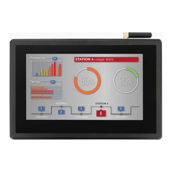
Side View 2 Product Overview ® The Cortex -A72/53 series EPC/PPC-A72-070-C (PN: CS10600R070) is a high-quality industrial panel PC. It features a 7.0” five-point capacitive touch screen with a resolution of 1024 x 600 pixels and brightness of 500 cd/m . -
Page 5: Ordering Options
It also provides a complete set of peripheral interfaces. Ordering Options Chipsee products can be customized during the ordering process. The product will be shipped with the pre-installed factory defaults if no extra requirements are specified. The... -
Page 6: Optional Features
Software Documentation section provides a detailed instruction on how to install different OSes on your own. However, bear in mind that Chipsee can’t take the responsibility of inadequate installation procedure. If you “brick” your device, please contact Chipsee Technical Support at support@chipsee.com... -
Page 7: Power Input
Power Input The EPC/PPC-A72-070-C Industrial Panel PC can be powered by a wide range of input voltages: From 12V to 36V DC. The power input connector is a 3-pin, 3.81mm terminal. The polarity and the pinout is clearly marked on the housing of the product as shown on the figure below. -
Page 8: Touch Screen
Ground Power System Ground Table 81 Power Connector Note The system ground “G” is connected to power negative “-” on board. Touch Screen The EPC/PPC-A72-070-C Industrial Panel PC uses a 5-point capacitive touch screen. Chipsee Page 8 of 21... -
Page 9: Connectivity
Use a high-quality Power Adapter Unit (PSU) with low EMR. You can also provide power from a battery. Make sure that the EPC/PPC-A72-070-C Power Input connector (pin 3) is properly connected to the Power System Ground to provide sufficient EMI shielding and eliminate the problem entirely. - Page 10 EPC/PPC-A72-070-C RS232+RS485 Connector Figure 390: Relation between serial pins on embedded vs. enclosed version The table below offers more detailed description of every pin and its definition: RS232 / RS485 / CAN Pin Definition: Pin Number Definition Description Pin 1...
-
Page 11: Usb Connectors
EPC/PPC-A72-070-C USB Connectors RS232 / RS485 / CAN Pin Definition: Pin 10 RS232_0_TXD USB UART0, RS232 TXD signal Pin 11 CPU_RS232_4_RXD CPU UART4, CPU RS232 RXD signal Pin 12 CPU_RS232_4_TXD CPU UART4, CPU RS232 TXD signal Pin 13 CPU_RS232_2_RXD CPU UART2, CPU RS232 RXD signal... -
Page 12: Lan Connectors
Use CAT5 or better cables to achieve full data throughput over maximum distance defined by the 1000BASE-T standard (100m). WiFi & BT Module The EPC/PPC-A72-070-C Industrial Panel PC is equipped with the popular Realtek RTL8723 WiFi/BT module that supports BT/BLE 4.0 (with backward compatibility), as well as 802.11bgn 2.4 GHz Wireless LAN (WLAN). -
Page 13: 4G/Lte Module
4G/LTE module. The customer will also need a SIM Card Holder and a 4G/ LTE Antenna Connector to ensure 4G/LTE works on the EPC/PPC-A72-070-C. SIM card does NOT support hot plug. Power off before inserting or removing SIM card. -
Page 14: Gpio Port
The product does not come shipped with the 4G/LTE module by default. GPIO Port The EPC/PPC-A72-070-C Industrial Panel PC has a 10 Pin 3.81mm GPIO Connector, as shown on the figure below, that is labeled as P18 on the PCB. The table below gives details about the definition of every Pin. - Page 15 EPC/PPC-A72-070-C GPIO Port Figure 398: GPIO Connector Chipsee Page 15 of 21...
-
Page 16: Tf Card Slot
The 4 output channels can drive at most 500mA current on each channel. TF Card Slot The EPC/PPC-A72-070-C Industrial Panel PC features 1 x TF Card (micro SD) slot. It can address up to 128GB of memory. Figure 399: TF (micro SD) Card Slot ... -
Page 17: Audio Connectors
The product does not come shipped with the TF Card by default. Audio Connectors The EPC/PPC-A72-070-C Industrial Panel PC features some audio peripherals, as well. It has 1 x 3.5mm audio input jack and 1 x 3.5mm audio output jack. -
Page 18: Power Button
EPC/PPC-A72-070-C Power Button Power Button The EPC/PPC-A72-070-C Industrial Panel PC has a power button, as shown on the figure below. You can use the button to power ON or OFF the industrial PC. Figure 403: Power Button Mounting Procedure The EPC/PPC-A72-070-C Industrial Panel PC can be mounted with 4 x M4 screws, enabling simplified installation onto any standard mounting fixture. -
Page 19: Mechanical Specifications
EPC/PPC-A72-070-C Mechanical Specifications Figure 405: Panel mounting Attention Please make sure the display is not exposed to high pressure when mounting into an enclosure. You can find detailed information about mounting in the Mount IPC Guide. Mechanical Specifications EPC-A72-070-C The outer mechanical dimensions of EPC-A72-070-C are 190 x 107 x 27.7mm (W x L x H). -
Page 20: Ppc-A72-070-C
Also, when the product is powered OFF, please take anti-static measures before touching the circuit board. 3D Model EPC/PPC-A72-070-C 3D model can be viewed in the online doc in a web browser, if you are reading from the PDF version, please visit the online doc. -
Page 21: Disclaimer
If you cannot find the solution you’re looking for, feel free to contact us. Please email Chipsee Technical Support at support@chipsee.com, providing all relevant information. We value your queries and suggestions and are committed to providing you with the assistance you require.
Need help?
Do you have a question about the EPC/PPC-A72-070-C and is the answer not in the manual?
Questions and answers