
Related Manuals for Chipsee EPC/PPC-A9-097-C


Summary of Contents for Chipsee EPC/PPC-A9-097-C
- Page 1 Industrial PC EPC/PPC-A9-097-C PN: CS10768F097 Content can change at anytime, check documentation website for latest information. www.chipsee.com...
-
Page 2: Table Of Contents
Contents 1. EPC/PPC-A9-097-C 1.1. Product Overview 1.2. Ordering Options 1.2.1. Operating System 1.2.2. Optional Features 1.3. Hardware Features 1.4. Power Input 1.5. Touch Screen 1.6. Connectivity 1.6.1. RS232/RS485/CAN 1.6.2. USB Connectors 1.6.3. LAN Connectors 1.6.4. WiFi & BT Module 1.6.5. 4G/LTE Module 1.6.6. -
Page 3: Epc/Ppc-A9-097-C
EPC/PPC-A9-097-C EPC/PPC-A9-097-C Front View Rear View Chipsee Page 3 of 20... -
Page 4: Product Overview
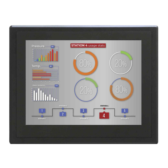
Front View (Embedded Variant) Rear View (Embedded Variant) Product Overview ® The Cortex -A9 series EPC/PPC-A9-097-C (PN: CS10768F097) is a rugged, high-quality industrial panel PC. It features a 9.7” multi-point capacitive touch screen with a resolution of 1024 x 768 pixels. Key Applications •... -
Page 5: Ordering Options
-40 to +125°C, the APU itself is well suited for extended temperature range in both automotive and factory environments. Ordering Options Chipsee products can be customized during the ordering process. The product will be shipped with the pre-installed factory defaults if no extra requirements are specified. The table in the... -
Page 6: Operating System
Software Documentation section provides a detailed instruction how to install different OS on your own. However, bear in mind that Chipsee can’t take the responsibility of inadequate installation procedure. If you “brick” your device, please contact Chipsee Technical Support at support@chipsee.com... - Page 7 EPC/PPC-A9-097-C Hardware Features EPC/PPC-A9-097-C ® ® iMX6Q, Arm Cortex -A9, 1GHz 2GB DDR3 eMMC Storage TF Card, Supports up to 32GB SDHC Display 9.7” LCD, 1024 x 768, High Brightness: 500cd/m Touch Capacitive Multi-Point Touch Screen 2 x USB 2.0 HOST, 1 x USB OTG 2 x RJ45: 1 x GbE, Optional PoE Support;...
-
Page 8: Power Input
Power Input The EPC/PPC-A9-097-C Industrial Panel PC can be powered by a wide range of input voltages: From 12V to 36V DC. The power input connector is a 3-pin, 3.81mm terminal. The polarity and the pinout is clearly marked on the housing of the PPC version, as well as on the PCB itself of the EPC version, as shown in the figure below. -
Page 9: Connectivity
Use a high-quality Power Adapter Unit (PSU) with low EMR. You can also provide power from a battery. Make sure that the EPC/PPC-A9-097-C Power Input connector (pin 3) is properly connected to the Power System Ground to provide sufficient EMI shielding and eliminate the problem entirely. - Page 10 EPC/PPC-A9-097-C RS232/RS485/CAN Figure 19: Serial pins connector The table below offers more detailed description of every pin and its definition: RS232 / RS485 / CAN Pin Definition: Pin Number Definition Description Pin 16 CAN2_H CPU CAN Channel 2 H signal...
-
Page 11: Usb Connectors
System 5V output, up to 1A Table 8 Connectivity Section 2(1,2)UART2 signal is used by the onboard WiFi/BT module, so the I/O port function is disabled by default. If you need the I/O port function instead, please contact Chipsee Technical Support at support@chipsee.com assistance. -
Page 12: Lan Connectors
Use CAT5 or better cables to achieve full data throughput over maximum distance defined by the 1000BASE-T standard (100m). WiFi & BT Module The EPC/PPC-A9-097-C Industrial Panel PC is equipped with the popular Realtek RTL8723 WiFi/BT module that supports BT/BLE 4.0 (with backward compatibility), as well as 802.11bgn 2.4 GHz Wireless LAN (WLAN). -
Page 13: 4G/Lte Module
Figure 24: WiFi+BT Antenna 4G/LTE Module The EPC/PPC-A9-097-C Industrial Panel PC is equipped with a mini-PCIe connector that can connect to a 4G/LTE module. The customer will also need a SIM Card Holder and a 4G/LTE Antenna Connector to ensure 4G/LTE works on the EPC/PPC-A9-097-C. SIM card does NOT support hot plug. -
Page 14: Gpio Connector
The product does not come shipped with the 4G/LTE module by default. GPIO Connector The EPC/PPC-A9-097-C Industrial Panel PC has a 10 Pin 3.81mm GPIO Connector, as shown in the figure below, that is labeled as P28 on the PCB. The table below gives details about the definition of every Pin. - Page 15 EPC/PPC-A9-097-C GPIO Connector Isolated GPIO reduced schematic GPIO Connector Pin Definition: Pin Number Definition Description Pin 1 Isolated Power +5V Output Pin 2 Isolated Ground Pin 3 OUT1 Isolated Output 1 Pin 4 OUT2 Isolated Output 2 Pin 5 OUT3...
-
Page 16: Tf Card Slot
The 4 output channels can drive at most 500mA current on each channel. TF Card Slot The EPC/PPC-A9-097-C Industrial Panel PC features 1 x TF Card (micro SD) slot. It can address up to 32GB of memory. Figure 27: TF (micro SD) Card Slot ... -
Page 17: Hdmi Connector
Figure 30: HDMI Connector Boot DIP Switch The EPC/PPC-A9-097-C Industrial Panel PC supports boot from SD card. If you want to re- flash the Operating System (OS), you can use the TF card for that purpose, combined with the DIP switch settings. -
Page 18: Mounting Procedure
Table 10 Boot Configuration Selection Mounting Procedure The EPC/PPC-A9-097-C Industrial Panel PC can be mounted with 8 x M4 screws, enabling simplified installation onto any standard mounting fixture. Other mounting options might also be supported according to the table in the Hardware Features section. - Page 19 EPC/PPC-A9-097-C PPC-A9-097-C Figure 32: Fixing PPC-A9-097-C industrial PC into panel Note With the PPC-A9-097-C industrial PC, the operator can fix the PC into the panel by pushing it from the front inside the panel as described in the figure above. The recommended maximum thickness of the panel material is 8mm.
-
Page 20: Disclaimer
If you cannot find the solution you’re looking for, feel free to contact us. Please email Chipsee Technical Support at support@chipsee.com, providing all relevant information. We value your queries and suggestions and are committed to providing you with the assistance you require.
Need help?
Do you have a question about the EPC/PPC-A9-097-C and is the answer not in the manual?
Questions and answers