Table of Contents
Advertisement
Quick Links
Advertisement
Table of Contents

Related Manuals for Chipsee EPC-CM3-070


Summary of Contents for Chipsee EPC-CM3-070
- Page 1 Industrial PC EPC/PPC-CM3-070 PN: CS10600RA070 Revision 1.1 www.chipsee.com...
-
Page 2: Table Of Contents
1.6.5. WiFi & BT Module 1.6.6. 3G/4G/LTE Module 1.7. TF Card Slot 1.8. Audio Connectors 1.9. Boot DIP Switch 1.10. Mounting Procedure 1.10.1. CS10600RA070E 1.10.2. CS10600RA070P 1.11. Mechanical Specifications 1.11.1. CS10600RA070E 1.11.2. CS10600RA070P 1.12. Disclaimer 1.13. Technical Support Chipsee Page 2 of 18... -
Page 3: Epc/Ppc-Cm3-070
EPC/PPC-CM3-070 EPC/PPC-CM3-070 Front View Rear View Chipsee Page 3 of 18... -
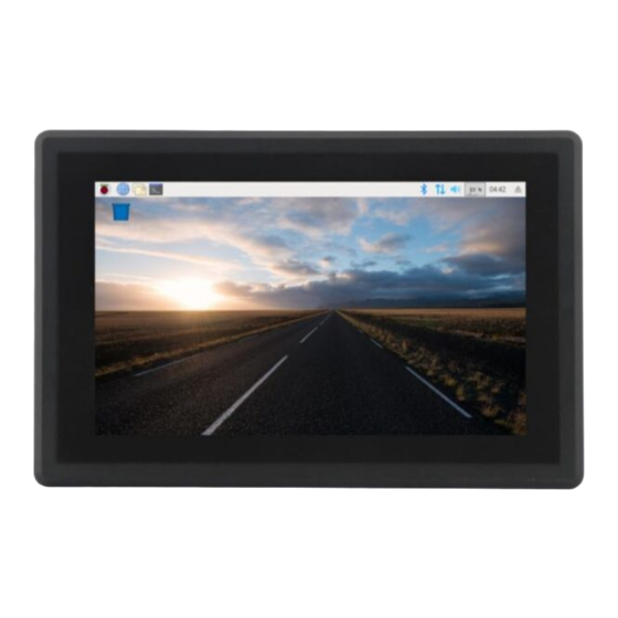
Page 4: Product Overview
Pi PC. It features a 7.0” five-point capacitive touch screen with a resolution of 1024 x 600 pixels and brightness of 500 cd/m . Key Applications • Human Machine Interface HMI • Process Control • Process Monitoring Chipsee Page 4 of 18... -
Page 5: Ordering Options
Optional Features The EPC/PPC-CM3-070 industrial Pi PC does not include the 3G/4G/LTE modules by default. These modules are optional and can be selected at the Chipsee store during the ordering process. Chipsee Page 5 of 18... -
Page 6: Specifications
Warning Installation, repair, and maintenance tasks should be performed by trained personnel only. Chipsee does not bear any responsibility for damage caused by inadequate handling of the product. Specifications The EPC/PPC-CM3-070 industrial Pi PC offers a board range of performance and connectivity options for scalable integration, providing expandability according to future needs. -
Page 7: Power Input
The RS485 multiplexes with the RS232_1, which means that you cannot use RS232_1 and RS485 at the same time. Chipsee designed one of the TF card slots for Lite version but it does not have an eMMC. We designed the other one for storage expansion. -
Page 8: Touch Screen
Use a high-quality Power Adapter Unit (PSU) with low EMR. You can also provide power from a battery. Make sure that the EPC/PPC-CM3-070 Power Input connector (pin 3) is properly connected to the Power System Ground to provide sufficient EMI shielding and eliminate the problem entirely. Chipsee Page 8 of 18... -
Page 9: Connectivity
CPU UART1, CPU RS232 TXD signal Pin 4 RS232_0_RXD CPU UART0, CPU RS232 RXD signal Pin 3 RS232_0_TXD CPU UART0, CPU RS232 TXD signal Pin 2 System Ground Pin 1 System +5V Power Output, No more than 1A Current output Chipsee Page 9 of 18... -
Page 10: Gpio Port
OUT3 Isolated Output 3 Pin 5 OUT4 Isolated Output 4 Pin 4 Isolated Input 1 Pin 3 Isolated Input 2 Pin 2 Isolated Input 3 Pin 1 Isolated Input 4 Table 209 GPIO Connector Pin-out Chipsee Page 10 of 18... -
Page 11: Usb Connectors
The product has one USB OTG connector that works as a slave by default. You can use it to establish a connection with the host PC and for downloading the system to the eMMC of CM3/CM3+. Figure 879: USB OTG Connector Warning Chipsee Page 11 of 18... -
Page 12: Lan Connectors
WiFi & BT Module The EPC/PPC-CM3-070 industrial Pi PC is equipped with the popular Realtek RTL8723 WiFi/ BT module that supports BT/BLE 4.0 (with backward compatibility), as well as 802.11bgn 2.4 GHz Wireless LAN (WLAN). Chipsee Page 12 of 18... -
Page 13: 3G/4G/Lte Module
The EPC/PPC-CM3-070 industrial Pi PC is equipped with a mini-PCIe connector that can connect to a 3G/4G module. The customer will also need a SIM Card Holder and a 3G/4G Antenna Connector to ensure 3G/4G works on the EPC/PPC-CM3-070. Figure 883: 3G/4G Module Chipsee Page 13 of 18... -
Page 14: Tf Card Slot
Figure 885: TF (micro SD) Card Slot Note The product does not come shipped with the TF Card by default. Audio Connectors The EPC/PPC-CM3-070 industrial Pi PC features some audio peripherals. It has 1 x 3.5mm audio output jack. Chipsee Page 14 of 18... -
Page 15: Boot Dip Switch
There is no need to alter the DIP switch settings during regular operation. However, if you need to reinstall the OS, please refer to the detailed information on how to re-flash the OS from the Software Documentation. Figure 887: Boot DIP Switch Chipsee Page 15 of 18... -
Page 16: Mounting Procedure
Figure 889: Panel mounting Attention Please make sure the display is not exposed to high pressure when mounting into an enclosure. You can find detailed information about mounting in the Mount IPC Guide. Chipsee Page 16 of 18... -
Page 17: Mechanical Specifications
Please refer to the technical drawing in the figure below for details related to the specific product measurements. Figure 890: CS10600RA070E Technical Drawing CS10600RA070P For CS10600RA070P, the outer mechanical dimensions are 206 x 135 x 30.1mm (W x L x H). Chipsee Page 17 of 18... -
Page 18: Disclaimer
If you cannot find the solution you’re looking for, feel free to contact us. Please email Chipsee Technical Support at support@chipsee.com, providing all relevant information. We value your queries and suggestions and are committed to providing you with the assistance you require.
Need help?
Do you have a question about the EPC-CM3-070 and is the answer not in the manual?
Questions and answers