
Related Manuals for Chipsee PPC-A8-080-R


Summary of Contents for Chipsee PPC-A8-080-R
- Page 1 Industrial PC EPC/PPC-A8-080-R PN: CS80600T080 Content can change at anytime, check our website for latest information of this product. www.chipsee.com...
-
Page 2: Table Of Contents
6.5. 3G/4G/LTE Module 6.6. GPIO Port 7. TF Card Slot 8. Audio Connectors 9. Boot DIP Switch 10. Mounting Procedure 11. Mechanical Specifications 11.1. EPC-A8-080-R 11.2. PPC-A8-080-R 12. 3D Model 13. Disclaimer 14. Technical Support Chipsee Page 2 of 29... -
Page 3: Epc/Ppc-A8-080-R
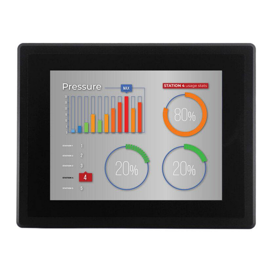
EPC/PPC-A8-080-R EPC/PPC-A8-080-R Front View Chipsee Page 3 of 29... - Page 4 EPC/PPC-A8-080-R Rear View Chipsee Page 4 of 29...
- Page 5 EPC/PPC-A8-080-R Front View (Embedded Variant) Chipsee Page 5 of 29...
- Page 6 EPC/PPC-A8-080-R Rear View (Embedded Variant) Chipsee Page 6 of 29...
-
Page 7: Product Overview
Product Overview Product Overview ® The Cortex -A8 series EPC/PPC-A8-080-R (PN: CS80600T080) is a high-quality industrial PC. It features a 8.0” resistive touch screen with a resolution of 800 x 600 pixels and brightness of 250 cd/m . Key Applications •... -
Page 8: Ordering Options
Software Documentation section provides a detailed instruction how to install different OS on your own. However, bear in mind that Chipsee can’t take the responsibility of inadequate installation procedure. If you “brick” your device, please contact Chipsee Technical Support at support@chipsee.com... -
Page 9: Optional Features
Both the Wi-Fi/BT and 3G/4G LTE module module are optional and can be selected during the ordering process. Warning Installation, repair, and maintenance tasks should be performed by trained personnel only. Chipsee does not bear any responsibility for damage caused by inadequate handling of the product. Chipsee Page 9 of 29... -
Page 10: Hardware Features
EPC/PPC-A8-080-R Hardware Features Hardware Features The EPC/PPC-A8-080-R Industrial PC offers a board range of performance and connectivity options for scalable integration, providing expandability according to future needs. Some of the key features are listed in the table below. EPC/PPC-A8-080-R ®... - Page 11 EPC/PPC-A8-080-R Hardware Features EPC/PPC-A8-080-R EPC-A8-080-R (PN: CS80600T080E): Embedded Mounting PPC-A8-080-R (PN: CS80600T080P): Panel Table 199 Key Features 1(1,2)The RS485 and CAN channels may be customized to the following arrangement: • 2 x RS485, 1 x CAN (Default) • 1 x RS485, 2 x CAN...
-
Page 12: Power Input
Power Input Power Input The EPC/PPC-A8-080-R Industrial PC can be powered by a wide range of input voltages: From 6V to 42V DC. The power input connector is a 3-pin, 3.81mm terminal. The polarity and the pinout is clearly marked on the housing of the PPC version, as well as on the PCB itself of the EPC version, as shown in the figure below. -
Page 13: Touch Screen
Touch screen Touch screen EPC/PPC-A8-080-R is equipped with a resistive touch screen. The resistive touch screen is an ideal option for harsh industrial conditions due to its high immunity against high temperature, dirt, and dust. In addition, it does not require any special material to be operated;... -
Page 14: Connectivity
The serial communication interfaces (RS485, RS232, and CAN) are routed to a 12-pin 3.81mm terminal, as illustrated on the figure below. Figure 668: Relation between serial pins on embedded vs. enclosed version of the EPC/PPC-A8-080-R Industrial PC The table below offers more detailed description of every pin and its definition:... - Page 15 EPC/PPC-A8-080-R RS232/RS485/CAN RS232 / RS485 / CAN Pin Definition: Pin 3 CAN_H DCAN0 of CPU, CAN H Signal Pin 2 CAN_L DCAN0 of CPU, CAN L Signal Pin 1 Isolated Ground Output Table 201 Connectivity Section Chipsee Page 15 of 29...
-
Page 16: Usb Connectors
EPC/PPC-A8-080-R USB Connectors USB Connectors There are 4 x Type A USB HOST connectors onboard, as shown on the figure below. Figure 669: USB HOST Connectors (embedded/enclosed PC version) Note The USB Connectors are defined as HOST by default. If customer needs it work as OTG (slave), please solder a 0Ω... -
Page 17: Lan Connectors
EPC/PPC-A8-080-R LAN Connectors LAN Connectors LAN (RJ45) connector provides Ethernet connectivity over standardized Ethernet cables as shown the figure below. The integrated Ethernet interface supports up to 1 Gbps data throughput. Figure 670: RJ45 LAN Connectors (embedded/enclosed PC version) ... -
Page 18: Wifi & Bt Module
The product does not come shipped with the WiFi/BT module by default. If the operator mounts the WiFi/BT module on the EPC/PPC-A8-080-R industrial PC, the module uses the USB1 channel to communicate with CPU, so it will occupy the USB1 channel. -
Page 19: 3G/4G/Lte Module
3G/4G/LTE Module 3G/4G/LTE Module The EPC/PPC-A8-080-R Industrial PC is equipped with a mini-PCIe connector that can connect to a 3G/4G/LTE module. The customer will also need a SIM Card Holder and a 3G/ 4G/LTE Antenna Connector to ensure 3G/4G/LTE works on the EPC/PPC-A8-080-R. -
Page 20: Gpio Port
GPIO Port GPIO Port The EPC/PPC-A8-080-R Industrial PC has a 10 Pin 3.81mm GPIO Connector, as shown on the figure below, that is labeled as P18 on the PCB. The table below gives details about the definition of every Pin. - Page 21 EPC/PPC-A8-080-R GPIO Port Isolated GPIO reduced schematic GPIO Connector Pin Definition: Pin Number Definition Description Pin 1 Isolated Power +5V Output Pin 2 Isolated Ground Pin 3 OUT1 Isolated Output 1 Pin 4 OUT2 Isolated Output 2 Pin 5 OUT3...
-
Page 22: Tf Card Slot
EPC/PPC-A8-080-R TF Card Slot TF Card Slot The EPC/PPC-A8-080-R Industrial PC features 1 x TF Card (micro SD) slot. It can address up to 32GB of memory. Figure 676: TF (micro SD) Card Slot Note The product does not come shipped with the TF Card by default. -
Page 23: Audio Connectors
Audio Connectors Audio Connectors The EPC/PPC-A8-080-R Industrial PC features some audio peripherals, as well. It has 1 x 3.5mm audio input jack and 1 x 3.5mm audio output jack. On the embedded panel PC version, the pink connector is the audio input jack (line-in) and the blue connector is the audio output jack (line-out, typically around -10 dBV). -
Page 24: Boot Dip Switch
Boot DIP Switch Boot DIP Switch The EPC/PPC-A8-080-R Industrial PC supports boot from SD card. If you want to reflash the Operating System (OS), you can use the TF card for that purpose, combined with the DIP switch settings as illustrated in the figure below. -
Page 25: Mounting Procedure
EPC/PPC-A8-080-R Mounting Procedure Mounting Procedure The EPC/PPC-A8-080-R Industrial PC can be mounted with 8 x M4 screws, enabling simplified installation onto any standard mounting fixture. Other mounting options might also be supported according to the table in the Hardware Features section. -
Page 26: Mechanical Specifications
The outer mechanical dimensions of EPC-A8-080-R are 199 x 149 x 29mm (W x L x H). PPC-A8-080-R For PPC-A8-080-R, the outer mechanical dimensions are 226 x 175 x 31mm (W x L x H). Chipsee Page 26 of 29... - Page 27 Note With the PPC-A8-080-R industrial PC, the operator can fix the PC into the panel by pushing it from the front inside the panel as described in the figure above. The recommended maximum thickness of the panel material is 8mm.
-
Page 28: D Model
As of Mar 23, 2024, the 3D asset of the product is being actively prepared, and will be available soon. EPC/PPC-A8-080-R 3D model can be viewed in the online doc in a web browser, if you are reading from the PDF version, please visit the online doc EPC/PPC-A8-080-R, select hardware documentation, drag the navigation bar to the 3D Model section. -
Page 29: Disclaimer
If you cannot find the solution you’re looking for, feel free to contact us. Please email Chipsee Technical Support at support@chipsee.com, providing all relevant information. We value your queries and suggestions and are committed to providing you with the assistance you require.
Need help?
Do you have a question about the PPC-A8-080-R and is the answer not in the manual?
Questions and answers