
Subscribe to Our Youtube Channel
Related Manuals for Tar River BDR 210


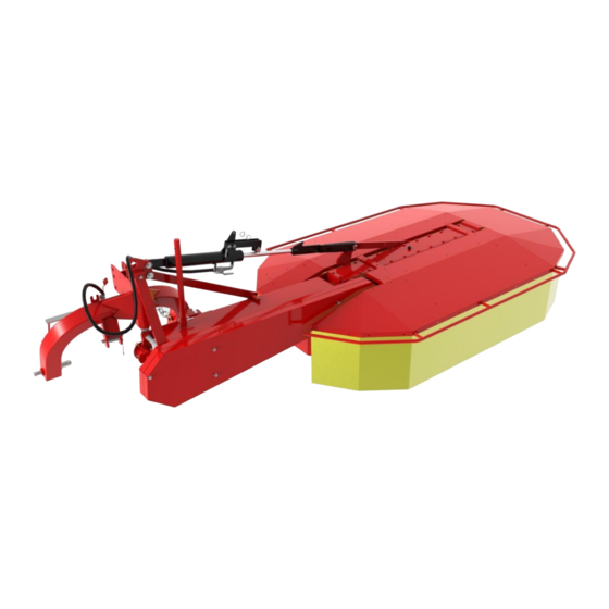
Summary of Contents for Tar River BDR 210
- Page 1 ORIGINAL USER MANUAL SPARE PARTS CATALOG BDR 210 Rotary Mower Tar River Equipment 2020 Edition 1...
- Page 2 ATTENTION! Before using the machine, please thoroughly read this User Manual and observe the safety instructions contained herein. The User Manual constitutes an inherent part of the machine! Keep the User Manual in a safe place, where it should be accessible to the machine operator during an entire lifespan of the machine.
- Page 3 Manufacturer guarantees the efficient operation of the machine, providing it is being used in accordance with the technical and operating conditions specified in this USER MANUAL. Any faults revealed during the warranty period will be repaired by the Warranty Service. Expiration date of the warranty period is specified in the WARRANTY CARD.
-
Page 4: Table Of Contents
Disassembly, utilization and environment protection ..............29 Spare Parts Catalogue ........................30 9.1. How to order spare parts ....................... 30 9.2. General construction – BDR 210 mower ................31 9.2.1. Suspension system ..........................32 9.2.1. Middle frame ............................33 9.2.2. -
Page 5: Introduction
Introduction Before the first use of the mower, you must thoroughly read and understand this User Manual, and follow all the instructions contained herein. ATTENTION! Before first use, read the User Manual This User Manual describes hazards, which may occur when you do not follow the safety precautions when operating and maintaining the mower. -
Page 6: Machine Identification
Machine identification Each mower has its rating plate, containing the most important identification data. The rating plate is located on the machine in a place, where it is easy to find and read. xxxxxx Fig. 1 Rating plate The rating plate includes: - full name of distributor - mower serial number - mower model... -
Page 7: Rules Of Safe Operation
Rules of safe operation 3.1. User safety The rotary mower can only be used by adults, who have learned its operation and read this User Manual, and are properly qualified. Mowers should be handled with all safety precautions, and in particular: •... - Page 8 • The mower must be adjusted to working height, during its attachment to the vehicle. During the mower operation certain adjustment is possible, it should be done from the inside of vehicle cabin, and operator should never leave the cabin. •...
-
Page 9: Residual Risk Assessment
• Mowing may be started only after PTO reaches the nominal speed of 540 rpm. It is forbidden to overload the PTO shaft of the mower, and engage the clutch suddenly. • When turning, reversing or manoeuvring with the machine, you must ensure that your visibility is adequate, or get assistance from a properly trained person. - Page 10 Hazard Hazard source (cause) Hazard protection measures Drive system Work in a standing, forced-bent Reading and understanding the User Manual, overload (physical position, walking, moving items workplace training including lifting standards weight) for the manual transportation labour, proper techniques for lifting and carrying weights, use of another person's assistance, moving equipment such as jacks, winches Fall on the same...
-
Page 11: Safety Signs On The Machine And Their Meaning
Too high rotational speed of Work only with the machine in good Noise the machine, damaged, loose, mechanical condition, regular inspections, vibrating parts proper rotational speed, familiarization with the User Manual 3.3. Safety signs on the machine and their meaning 1.1 - Switch off the engine and 1.2 - Keep a safe distance from remove the ignition key before... - Page 12 1.0 - Prior to using the machine, beginning any servicing or unauthorized persons within read the User Manual maintenance procedures the range of 50 m from the machine 1.5 - Do not stand near the 1.4 - Do not ride on platforms and lifting jack connectors, when ladders controlling the jack...
-
Page 13: Intended Use Of The Machine
2.2 – 2.6 – Use protection Warning message about pressure 2.5 – Use hearing goggles in the hydraulic system protectors 2.9 Do not exceed the maximum RPM Table 1 Safety signs on the machine and their meaning Intended use of the machine The rotary mower is designed for agricultural applications, mowing of the low growing green forage like grasses, alfalfa, etc., on fields and meadows with flat surfaces. -
Page 14: Equipment And Accessories
The distributor offers a wide range of agricultural machinery. It can also provide professional advice in terms of choosing the right equipment for your needs. Any doubts concerning the machine’s intended use should be resolved by contacting its distributor. Selection of the appropriate product and knowing the range of its intended use will contribute to the occupational safety. - Page 15 Figure 2 Overall machine construction: 1 - suspension frame; 2 – main chassis; 3 – hydraulic cylinder (depending on the model); 4 – cutting unit; 5 – cover assembly; 6 – working section of cutting unit; 7 – support foot. Suspension system frame is used to connect the mower to a tractor.
-
Page 16: Machine Usage
Mower model Eco CUT Type 2.10m Symbol Z-042/3 Type of mower Rotary suspended 2.10 Mowing width Power requirement [kW] Number of cutting drums [pcs.] Number of blades [pcs.] Standard cutting height [mm] Low cutting height [mm] [rpm] 1545 Rotational speed of working drums Rotational speed of tractor’s PTO [rpm] [cat.]... -
Page 17: Mower Assembly
6.1. Mower assembly The distributor delivers a complete mower with a cover of the cutting unit. Installation of the cutting unit cover must be done by the user or dealer. Working without the cutting unit cover, or with the cover damaged or raised, poses a danger for an operator and for environment –... -
Page 18: Transport Position
Figure 3 Aggregating – connecting the mower In order to connect the mower to the tractor: 1. On the pins (Fig. 8, item1) of the suspension frame, fit the tractor’s lower connectors (first left, then right), and secure them with linchpins. 2. - Page 19 1) transport position 2) working position For mower models with hydraulic cylinder 2.10m: Park the tractor and mower on a flat, even surface, 2. Remove the securing element from the upper pivot of the suspension frame, 3. Raise the mower with a hydraulic cylinder of the tractor, so that the sliding discs do not rest on the ground, 4.
- Page 20 Figure 4 Proper transport position for 2.10m mowers Closing the cylinder for Eco CUT 210 mower for transport is shown in the figure below. Lock pin - Pos. 1 should lock into the cylinder handle (lower the mower until the pin is completely locked). The ball valve lever should be moved to the closed position - Pos.
-
Page 21: Working Position
6.4. Working position To transform the transportation position to the working position: 1. Park the tractor and mower on a flat, even surface, 2. In the mower with hydraulic cylinder, pull the rope to release the cylinder lock then move the mower to horizontal position. -
Page 22: Operation Of The Mower
6.6. Operation of the mower The mower is equipped with an overload break-back device, which allows pushing away the mower when it hits an obstacle or encounters too great resistance during cutting. To engage back the break-back device, reverse the tractor a short distance. Incorrect spring tension can cause incorrect operation of the machine, or even its damage. -
Page 23: Operation And Maintenance
Operation and maintenance All the machine operations can be performed by the operator of the vehicle, to which the machine is attached, providing that he/she has proper authorization to operate this vehicle. After disconnecting the machine from a vehicle, it should be stored under shelter on a flat and hard surface, supported on its foot. -
Page 24: Adjustment Of The V-Belts Tension
7.1. Adjustment of the V-belts tension The mower is equipped with a spring loaded belt tensioner. Correct tension of the belts can be checked through the inspection hole (Fig. 21). Properly tightened belts should give in slightly under the pressure of the operator’s hand. -
Page 25: Replacing The Blades
7.2. Replacing the blades: The cutting blades must be replaced in compliance with the specific safety rules: 1. Use only the original and functional parts for the cutting unit. 2. Each time the replacement must include the full set. You must remember about the uniform distribution of the rotating masses, to ensure the uniform wear of the blades. -
Page 26: Maintenance After Work
Damaged and worn out parts replace with new ones. Check all the bolted joints, tighten the loose bolts and nuts according to Table 3. Please note: Distributor of the machine, Tar River Equipment, provides all spare parts. Strength 10.9 12.9... -
Page 27: Lubrication
7.4. Lubrication All maintenance and servicing works should be done with the switched off engine of the vehicle, released pressure and stopped rotations, and with both, the vehicle and machine, properly secured. Avoid contact with oil! Use the personal protective equipment: protective clothing, footwear, gloves and goggles. -
Page 28: Possible Problems And Solutions
In the case of leaks from the hydraulic system, the damaged parts and components must be replaced to avoid contamination of the environment. Hydraulic hoses, regardless of their external condition, must be replaced after 5 years. 7.6. Possible problems and solutions Table 4 Possible problems and solutions Problem symptoms Problem cause... -
Page 29: Disassembly, Utilization And Environment Protection
Disassembly, utilization and environment protection Protect your hands (and body) against injuries, and the harmful effects of lubricants and oils. Use protective gloves and tools which are in good mechanical condition. Machine elements, which when dismounting can move or rotate, must be properly secure Worn or damaged parts removed during repair (disassembly) should be stored in a separate location, with a limited access for persons and animals. -
Page 30: Spare Parts Catalogue
Such changes may not always be updated in the User Manual and in the spare parts catalogue. Individual drawings may differ from the actual look of the parts. Tar River Implements 401 Jeffrey’s Road Rocky Mount, NC 27804 sales@brglimited.com... -
Page 31: General Construction - Bdr 210 Mower
General construction – BDR 210 mower 9.2. Pos. Description Index Suspension system 9.3.1 Middle frame 9.3.2 Hydraulic system 9.3.3 Metal cover 9.3.4 Main frame 9.3.5 Cutting unit 9.3.6... -
Page 32: Suspension System
9.2.1. Suspension system Pos. PART NO. Description Quantity DM301011 Suspension Frame DMT0404 Hitch Lock Spring CP5x40 Cotter Pin- M5 x 40 GALV DM30104 210 Blade Removal Tool DM30105 R-Clip- M4x100 double pin DMT0403 Suspension Frame Latch DM30107 Lower Hitch Pin LNM12175 Self-locking Nut- M12 x 1.75 GALV BM1217535... -
Page 33: Middle Frame
9.2.1. Middle frame... - Page 34 Pos. PART NO. Description Quantity DM30201 Outer V-belt Cover FW10 Flat Washer- M10 GALV LNM1015 Self-locking Nut M10 GALV SPB3550 V-belt- SPB 3550 SRE-35 Snap Ring- M35 (External) DM30206 Cover Pin BM0812520 Bolt- M8 x 1.25 x 20 GALV 8.8 DM30208 Large Pulley DM30209...
- Page 35 Safety Breakaway Device 9.2.1.1. Pos. PART NO. Description Quantity DM30301 Inner Bar DM30302 Outer Bar FW12 Flat Washer- M12 GALV BM1217535 Bolt- M12 x 1.75 x 35 GALV 8.8 DM30305 Breakaway Cube DM30306 Flat Middle Bar LNM142 Self-locking Nut- M14 GALV DM30308 Spring Rod DM30309...
-
Page 36: Hydraulic System
9.2.2. Hydraulic system... - Page 37 Pos. PART NO. Description Quantity DM30401 Hydraulic Cylinder for BDR210 FW22 Flat Washer- M22 GALV CP5x40 Cotter Pin- M5 x 40 GALV DM30404 Thin Flat Washer- M25 GALV DM150074 Pivot Pin- M22 x 55 GALV DM83002 Pivot Pin- M25 x 55 GALV DM150331 Hose P51/P51 M18x1,5/M16x1,5 DN8 2SN L- 2500...
-
Page 38: Metal Cover
9.2.1. Metal cover Pos. PART NO. Description Quantity DM30501 Plastic Protection Cover- M19 0.8-2.O DM30502 Right Safety Guard DM30503 Right Safety Cover DM30504 Reinforcement Plate DM30505 Reinforcement Bracket 2 DM30506 Rear Protection Cover DM30507 Rear Safety Guard DM30508 Reinforcement Bracket DM30509 Debris Safety Tarp 2.1 DM30510... -
Page 39: Main Frame
9.2.2. Main frame... - Page 40 Pos. PART NO. Description Quantity DM10075 Small Bearing Housing B6206 Bearing- 6206 DM30603 As needed- M0.3 ; Adjustment Washer- M30 x 42 0.5 or 1 DM30604 Large Conical Gear 21T DM30605 Main Frame DM30606 Pulley SPB 140 DM30607 Bushing- TB 2517/30 KM080745 Key- M8 x 7 x 45 DM30609...
-
Page 41: Cutting Unit - Working Part
9.2.1. Cutting unit – working part... - Page 42 Pos. PART NO. Description Quantity OS507210 Oil Seal- M50 x 72 x 10 DM30702 As needed, Adjustment Spacer Shim- M30 x 42 M0.3, 0.5 or M1 B63062RS 210 Bearing 6306 2RS SRI-72 210 Circlip 72W B62102RS 210 Bearing 6210 2RS DM30706 210 Cover DM30707...
- Page 43 Fitting instructions for the metal covers Attention! All bolted joints in steps I - VII should be initially only loosely connected - not tightened. The final tightening should be done after the cover has been placed on the main frame and adjusted to the machine - step XI of the covers fitting procedure.
- Page 44 1) STEP II • Fix bent reinforcements to left and right cover Figure 12 Step II Bent Reinforcement Assembly Rent reinforcement Bent Reinforcement Figure 13 Step II Bent Reinforcement Assembly The figure below shows which bolt elements were used in steps II to V. Case of use of other bolt elements, indicated below.
- Page 45 2) STEP III • Adjust and fix reinforcing angle bars to the left and right coves Reinforcing angle bar short Reinforcing angle bar Reinforcement holder Figure 15 Step III Reinforcing angle bars assembly 3) STEP IV • Adjust and fix the reinforcing holder to the holes in the left bent reinforcement and the left cover Reinforcement Holder Bent Reinforcement...
- Page 46 Pos. PART NO. Name BM0812520 Bolt- M8 x 1.25 x 25- GALV 8.8 DM30902 Reinforcement Holder FW08 Flat Washer- M8 GALV LNM08125 Nut 6-cat. self. M8 galv. Figure 16 Step IV Reinforcement holder assembly *GALV – galvanized coating Figure 17 Detail A of Figure 25 4) STEP V •...
- Page 47 Pos. PART NO Name CBM0812520 Carriage Bolt- M8 x 1.25 x 20- GALV 8.8 FW08 Flat Washer- M8 GALV LNM08125 Self-locking Nut- M8 GALV DM31004 Reinforcement Angle Bar DM31005 Right Cover Reinforcement *GALV – galvanized coating Figure 19 Detail A of Figure 27 STEP VI Adjust and fix the rear cover to the left and right covers, and to angle bars.
- Page 48 *GALV – galvanized coating Pos. PART NO Name BM0812516 Bolt- M8 x 1.25 x 16-GALV 8.8 FW08 Flat Washer- M8 GALV LNM08125 Self-locking Nut- M8 x 1.25 DM31104 Rear Cover Figure 21 Figure 29 Detail A 6) STEP VII Check if all the elements were properly fixed. Short Reinforcement Bracket Reinforcement Bracket Bent Reinforcement...
- Page 49 After initial attaching of the apron to the metal shield, bolt the apron together with the barriers to the metal guard in places marked in Figure 38 (below). Figure 38 Metal Guard assembly for BDR 210 Pos. PART NO Description Qty.
- Page 50 Attention! In the case of bolted joints fixing protective apron to metal cover, tighten the bolted joints according to Table 3. 8) STEP IX • Disconnect the milled connector from the scythe-connector (For models with hydraulic cylinder) (Fig. 37 item 2), •...
- Page 51 9) STEP X Unscrew the bolts indicated in the following figure (Fig. 39) - cover mounting location: Figure 39 Metal covers assembly – STEP X 10) STEP XI Adjust the cover to the "free holes" from STEP X and fix it with the bolt elements used in STEP Place the rear cover on the flat bar located on the main frame cover...
- Page 52 11) STEP XII Connect the scythe-connector with hydraulic cylinder, in reverse order from STEP IX 12) STEP XIII Fix the front cover to the main frame (Fig. 38). Item Part No. Name Index DM31201 Front cover BM061025 Bolt- M6 x 1.0 x 25 GALV 8.8 FW06 Flat washer M10 galv.
- Page 53 Position Part Number Description Qty. Yoke Inner Yoke complete Outer Yoke complete Inner PTO Guard Complete Outer PTO Guard Complete Cross & Bearing Safety Chain DM30242 PTO Shaft Complete...
- Page 54 WARRANTY WARRANTY CARD Factory no. Model ……………………… ……………………… Year of ……………………… ……………………… construction Under warranty, the distributor undertakes to repair free of charge any physical defects revealed during the warranty period, which lasts for 12 months from the date of sale. The manufacturer is exempt from any liability under the warranty in the case of: •...
-
Page 55: Records Of Warranty Repairs
Records of warranty repairs To be filled by the distributor Date of complaint claim: Date of complaint claim: The scope of repair and parts used: The scope of repair and parts used: Date of complaint resolution: Date of complaint resolution: Warranty period extended until: Warranty period extended until: (Dealer’s signature and stamp) -
Page 56: Warranty Form
Warranty form WARRANTY FORM NO. ……………… Full name: ........................Address: ......................... Post code: ……....................... City: ……......................... Telephone No: …......................Email address: …………………..................Reason for claim: ………...…………………………………………………………………... Persons Name: ......................Name of the dealer:…………….…………………………………........Proof of purchase- Invoice no.......Date: ........20....Description of damages: ............................
Need help?
Do you have a question about the BDR 210 and is the answer not in the manual?
Questions and answers