
Related Manuals for Tar River BDR-135


Summary of Contents for Tar River BDR-135
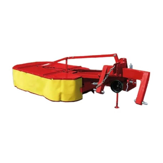
- Page 1 Drum Mower Models: BDR-135 BDR-165 BDR-185 Operator’s Manual Parts Breakdown Publication #: January 2014...
-
Page 2: Table Of Contents
TABLE OF CONTENTS Introduction Saftey Rules Partial Risks General Information Operational Service Connecting the Mower with the Tractor Assembly of the PTO Shaft Adjusting the Mower to Transport Position Adjusting the Mower to Operational Position Adjusting the Mower Operating the Mower Resting Position Technical Maintenance of the Mower Changing the Blades... -
Page 3: Introduction
INTRODUCTION Thank you for purchasing your Tar River Drum Mower. This Operator’s Manual is available with every machine for the purpose of introducing the user to the design, maintenance, and adjustment of the mower. It will also warn against any possible threats. The Operator’s Manual includes information regarding the adjustment and transport on the public roads. -
Page 4: Saftey Rules
SAFETY RULES PLEASE BE CAREFUL – READ THE OPERATOR’S MANUAL CAREFULY IN ORDER TO PROTECT YOURSELF AND OTHERS FROM DANGER. The machine should be used with respect to the basic work safety rules and the following precautions: NEVER allow any unauthorized per sons, unfamiliar with the Oper ator ’s Manual or under age per sons, especially children, to use the machine. -
Page 5: Partial Risks
PARTIAL RISKS The manufacturer has made every effort to ensure that the design and the intended method of operating the mower does not cause any danger to people and their environment. Due to the nature of the mower and the lack of such opportunities to fully expose the cutter, certain elements of risk can occur. -
Page 6: General Information
GENERAL INFORMATION Sales Information The technical condition and the equipment of the mower should be checked at the time of purchase. It should be required from the equipment dealer to carefully fill out the Warranty Registration Form. Failure to pro- vide the date of purchase or the dealer’s information might cause the buyer to suffer disapproval of any possible com- plaints. - Page 7 The suspension system frame (1) is used to connect the mower with the tractor. The main frame (4) is connected piv- otally with the suspension frame through the central beam (2). The cutting system is made of two operating drums (7) with blades attached rotationally in their lower part.
-
Page 8: Operational Service
OPERATIONAL SERVICE You may start operating the machine only after having carefully read the Operator’s Manual. Prior to connecting the rotary mower to the recommended tractors, they should be properly prepared. Check the physical condition of the machine and perform daily maintenance work in accordance to the operator’s manual of the tractor. -
Page 9: Assembly Of The Pto Shaft
IT IS UNACCEPTABLE for any persons to be present between the machine and the tractor while backing up to the machine to connect the machine while the tractor’s engine is on and the key is in the ignition ... -
Page 10: Adjusting The Mower To Transport Position
Adjusting the Mower to the Transport Position and Transport:... - Page 11 Be careful while changing the mower’s position from the transport position to the operating position and the other way around. It is prohibited to reposition the mower: On an uneven surface and in a visible slope area. When it is lifted high (as in the transport position), and when the suspension frame of the mower is not appropri- ately level.
-
Page 12: Adjusting The Mower To Operational Position
Adjusting the Mower to the Operational Position Reposition the mower from the transport position to the operating position prior to starting the operation. In order to do that, the following must be done: Place the unit (the mower and the tractor) on an even, horizontal surface. ... - Page 13 Changing the mower’s position from the transport position to the operating position and the other way back. Changing the mower’s position to the operating position...
-
Page 14: Adjusting The Mower
Adjusting the Mower Determining the length of the upper connector. After repositioning the mower to the operating position, the stump jumpers should be positioned parallel to the ground and the suspension frame should be positioned at such a height so the distance “a” is about 11 inches and the pin is in the middle of the longitudinal opening of the push rod (Drawing 2). - Page 15 1 bolt M12x25 2 stump jumper 3 bolt M12x30 4 spring washer Ø12 5 spacer 8mm or 12 mm 6 resistance disk 7 hub 8 operating disk 9 blade Drawing 3: Adjusting the height of cut. In order to change the height of cut from 40mm to 44mm, the 8mm spacer ring should be substituted with a 12mm spacer, and in order to achieve the 32 mm height of cut, the spacer ring should be disassembled.
-
Page 16: Operating The Mower
Operating the Mower The fields and meadows to be mowed should be free from any foreign and/or hard object or stones, which may dam- age the mower. The shields of the mower must be positioned downwards during operating of the machine. The mower’s drive should be turned on slowly and after reaching 540 RPM of the power take-off, the operation may be started. -
Page 17: Resting Position
Resting Position The mower in the resting position is completely separated from the tractor’s suspension system. The mower is repo- sitioned from the transport position to the resting position. The following should be done for that purpose: With the three point suspension system, the support of the mower should be lowered and secured with a cotter. ... -
Page 18: Technical Maintenance Of The Mower
TECHNICAL MAINTENANCE OF THE MOWER Changing the Blades In order to install or disassemble the blades on the operating disc, a special wrench key should be used, which is in- cluded in the basic equipment of the mower. Due to the sharp edges of the blades, protective gloves should be used in disassembling the blades. Changing the blades Installing the blades: ... -
Page 19: V-Belt Tension
When changing the blades holders, special attention should be paid to their positional relationship between the individual discs. Arrangement of the Blades: NOTE: Only certified blades should be used. V-Belt Tension Check the condition of the V-belt of the transmission; the flexibility under the finger pressure shouldn’t exceed 1 ¼”. The V-belts are stretched with a spring tensioner (Position 1 in the drawing below). -
Page 20: Everyday Maintenance
Everyday Maintenance Following operation, clean the mower from any plant residues or dirt and check its technical condition every day. Inspect the components and their connections. All loosened bolt connections should be tightened, and the worn out or damaged parts should be replaced with new original spare parts. - Page 21 The greasing points indicated by triangles should be greased with a machine oil with the help of a lubricator. The PTO shaft should be lubricated in accordance with the shaft manufacturer’s requirements. REMEMBER: The higher quality and viscosity 90 Wt. gear oil should be used or alter nately 140 Wt.
-
Page 22: Transport Lights
Transport Lights The mower should always be positioned horizontally or vertically in the driving direction (behind the tractor). During a transport, the machine must be equipped with the warning triangle sign (1) and a portable warning light de- vice (2) consisting of two rectangular plates painted with white and red stripes, to which composite tubes are assem- bled with side position lights, stop lights and turn signals. -
Page 23: Assembly Of Mower
Assembly of the Mower The manufacturer delivers a mower with the cutting system’s cover that is not assembled. The responsibility to install the covers is on the side of the purchaser. Operating the mower with the cutting system’s cover not installed or damaged or with the shield lifted is hazardous to the operators and the environment. -
Page 24: Troubleshooting
Dismantling, Utilization, and the Methods of Utilization. Protect your hands (body) from injuries and harmful effects of lubricants and oils. Use protective gloves and tools in good technical condition. The elements of the machine which may reposition or turn during the disassembling should be appropriately secured. The worn out or damaged parts obtained during repairs (dismantling) should be stored in a segregated place of limited accessibility to people and animals. -
Page 25: Parts Breakdown
PARTS BREAKDOWN Models: BDR-135 BDR-165 BDR-185... - Page 26 Belco Resources Equipment BDR-135 ~ BDR-165 ~ BDR-185 Central Beam - Suspension...
- Page 27 Belco Resources Equipment BDR-135 ~ BDR-165 ~ BDR-185 Position Part # Description DM90135 Main Frame BDM-135 DM90165 Main Frame BDM-165 DM90185 Main Frame BDM-185 FW10000 Washer NM10000 Nut M10 DM20175 Central Beam DM10180 Yoke Push Rod DM10088 Star Washer DM82105...
- Page 28 Belco Resources Equipment BDR-135 ~ BDR-165 ~ BDR-185 Central Beam - Suspension...
- Page 29 Belco Resources Equipment BDR-135 ~ BDR-165 ~ BDR-185 Position Part # Description DM20290 lock DM20760 Support Spring pin Lock pin DM83002 King pin Washer Ø25 Cotter pin Nut M16 Washer Ø16 Lock faceplate Spring Bolt M10x30 Bearing 6009 Securing ring Z45...
- Page 30 Belco Resources Equipment BDR-135 ~ BDR-165 ~ BDR-185 Standard Mower - Cotter Pins...
- Page 31 Belco Resources Equipment BDR-135 ~ BDR-165 ~ BDR-185 Position Part # Description LW12000 Washer Ø12 BM12175100 Bolt M12x100 NM12000 Nut M12 BM1217535 Bolt M12x35 DM83002 King pin DM82005 Washer Ø25 DM82001 Cotter pin DM20220 Locking bar DM10110 Main frame push rod...
- Page 32 Belco Resources Equipment BDR-135 ~ BDR-165 ~ BDR-185 Suspension &2 &8...
- Page 33 Belco Resources Equipment BDR-135 ~ BDR-165 ~ BDR-185 Position Part # Description Suspension structure Suspension pin - 135 & 165 Latch Spring Cotter pin Securing pin Chain Suspension pin - 185 FW24000 Washer Ø24 LN24000 Self locking counter nut M24...
- Page 34 Belco Resources Equipment BDR-135 ~ BDR-165 ~ BDR-185 Input Drive...
- Page 35 Belco Resources Equipment BDR-135 ~ BDR-165 ~ BDR-185 Position Part # Description DM20513 Driving head B6206 Bearing 6206 DM20602 Drive shaft SRE35000 Retaining ring Z35 DM21903 Shaft cover B6007 Bearing 6007 KM080756 Pin 8x7x56 DM20172 Carrier DM20205 Bushing DM20218 Spring...
- Page 36 Belco Resources Equipment BDR-135 ~ BDR-165 ~ BDR-185 Breakaway Bar...
- Page 37 Belco Resources Equipment BDR-135 ~ BDR-165 ~ BDR-185 Position Part # Description DM20290 Lower sliding bar DM20291 Upper sliding bar DM20322 Lock fuse BM1420260 Bolt M14x260 DM20310 Lock spacer sleeve FW14000 Washer Ø14 NM14000 Nut M14 DM20348 Spring DM20307 Spring cap...
- Page 38 Belco Resources Equipment BDR-135 ~ BDR-165 ~ BDR-185 Main Frame...
- Page 39 Belco Resources Equipment BDR-135 ~ BDR-165 ~ BDR-185 Position Part # Description DM10192-135 Frame-135 DM10192-165 Frame-165 DM10192-185 Frame-185 DM10365 Drum plug DM10721 Operating drum DM10156 Inlet 8x7x32 DM10019 Bevel gear DM85111 Retaining ring Z25 BM101525 Bolt M10x25 FW10000 Washer Ø10...
- Page 40 Belco Resources Equipment BDR-135 ~ BDR-165 ~ BDR-185 Main Frame...
- Page 41 Belco Resources Equipment BDR-135 ~ BDR-165 ~ BDR-185 Position Part # Description BM101560 Bolt M10x60 DM10075 Bearing casing II DM85023 Spring pin Ø6x12 DM10088 Star washer DM10047 Horizontal frame roller DM10090 Bevel gear DM10604 Inlet 8x7x50 Bearing casing I DM85111...
- Page 42 Belco Resources Equipment BDR-135 ~ BDR-165 ~ BDR-185 Covers...
- Page 43 Belco Resources Equipment BDR-135 ~ BDR-165 ~ BDR-185 Position Part # Description DM30015-135 Front shield-135 DM30015-165 Front shield-165 DM30015-185 Front shield-185 DM30069-135 Middle shield-135 DM30069-165 Middle shield-165 DM30069-185 Middle shield-185 DM30015-135 Rear shield-135 DM30015-165 Rear shield-165 DM30015-185 Rear shield-185 DM30043...
-
Page 45: Warranty
LIMITED WARRANTY Belco Resources Equipment warrants to the original purchaser of any new piece of machinery from Belco Resources Equipment, purchased from an authorized Belco Resources Equipment dealer, that the equipment be free from defects in material and work- manship for a period of one (1) year for non-commercial, state, and municipalities’ use, ninety (90) days for commercial use from date of retail sale.
Need help?
Do you have a question about the BDR-135 and is the answer not in the manual?
Questions and answers