Table of Contents
Advertisement
Quick Links
The Texas Instruments DS90UB95x-Q1EVM evaluation module (EVM) is a functional board design for
evaluating the DS90UB953-Q1 FPD-Link III serializer. This document provides necessary details for the
evaluation such as a brief product overview, quick-start guide, troubleshooting section, schematics, and
printed-circuit board (PCB) layout details, and bill of materials (BOM).
The DS90UB953-Q1 serializer represents the next generation in FPD-III serializers and is designed to
support high-speed raw data sensors including 2-MP imagers at 60 fps, as well as 4-MP, 30-fps cameras,
satellite RADAR, LIDAR, and time-of-flight (ToF) sensors. The chip delivers a 4-Gbps+ forward channel
and an ultra-low latency, 50-Mbps bidirectional control channel. The chip also supports power over a
single coax (PoC) or shielded twisted-pair (STP) cable and connector. The DS90UB953-Q1 features
advanced data protection and diagnostic features to support ADAS and autonomous driving. Together
with a companion deserializer, the DS90UB953-Q1 delivers precise multi-camera sensor clock and sensor
synchronization. For a full list of device characteristics, refer to the
The Texas Instruments DS90UB95x-Q1EVM evaluation module (EVM) is a functional board design for
evaluating the DS90UB953-Q1 FPD-Link III serializer. This document provides necessary details for the
evaluation such as a brief product overview, quick-start guide, troubleshooting section, schematics,
printed-circuit board (PCB) layout details, and a bill of materials (BOM).
...................................................................................................................
1
Introduction
2
Quick Start Guide
3
Troubleshooting
4
Bill of Materials
5
PCB Schematics
6
Board Layout
7
Related Documentation
1
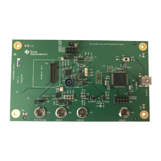
DS90UB95x-Q1EVM Top View
2
Typical Application Block Diagram Using DS90UB953-Q1 and DS90UB954-Q1 (or variant)
3
DS90UB95x-Q1EVM Major Components
4
DS90UB95x-Q1EVM With Installed Jumpers
5
DS90UB954-Q1EVM (or variant) With Jumpers Highlighted
.....................................................................................................................
6
USB2ANY
7
I2C Pinout of USB2ANY Connector
8
Launching ALP
9
Initial ALP Screen
10
Follow-Up Screen
11
ALP Information Tab
12
ALP Registers Tab
13
ALP Device ID Selected
14
ALP Device ID Expanded
15
Writing to Register 0x00 by Checking Bits in ALP
16
ALP Scripting Tab
17
Pre-Defined Scripts
SNLU224A – September 2017 – Revised May 2019
Submit Documentation Feedback
DS90UB95x-Q1 Serializer Evaluation Module
............................................................................................................
..............................................................................................................
.............................................................................................................
...........................................................................................................
................................................................................................................
....................................................................................................
............................................................................................
.......................................................................................
...............................................................................................................
..........................................................................................................
..........................................................................................................
.......................................................................................................
.........................................................................................................
...................................................................................................
.................................................................................................
..........................................................................................................
........................................................................................................
Copyright © 2017–2019, Texas Instruments Incorporated
SNLU224A – September 2017 – Revised May 2019
DS90UB953-Q1
Contents
List of Figures
................................................................................
............................................................................
..........................................................
.....................................................................
DS90UB95x-Q1 Serializer Evaluation Module
User's Guide
product folder.
3
4
7
36
40
47
53
3
.....................
4
5
5
6
7
8
9
10
10
11
12
13
14
14
15
16
1
Advertisement
Table of Contents

Related Manuals for Texas Instruments DS90UB95 Q1 Series


Summary of Contents for Texas Instruments DS90UB95 Q1 Series
- Page 1 SNLU224A – September 2017 – Revised May 2019 DS90UB95x-Q1 Serializer Evaluation Module The Texas Instruments DS90UB95x-Q1EVM evaluation module (EVM) is a functional board design for evaluating the DS90UB953-Q1 FPD-Link III serializer. This document provides necessary details for the evaluation such as a brief product overview, quick-start guide, troubleshooting section, schematics, and printed-circuit board (PCB) layout details, and bill of materials (BOM).
-
Page 2: Table Of Contents
Bottom Layer PCB Layout ......................Bottom Overlay ....................... Bottom Paste ....................... Bottom Solder List of Tables ........................Equipment ......................Bill of Materials DS90UB95x-Q1 Serializer Evaluation Module SNLU224A – September 2017 – Revised May 2019 Submit Documentation Feedback Copyright © 2017–2019, Texas Instruments Incorporated... - Page 3 Figure 1. DS90UB95x-Q1EVM Top View SNLU224A – September 2017 – Revised May 2019 DS90UB95x-Q1 Serializer Evaluation Module Submit Documentation Feedback Copyright © 2017–2019, Texas Instruments Incorporated...
- Page 4 50 Ÿ HS_GPIO HS_GPIO (SPI) (SPI) Copyright © 2016, Texas Instruments Incorporated Figure 2. Typical Application Block Diagram Using DS90UB953-Q1 and DS90UB954-Q1 (or variant) DS90UB95x-Q1 Serializer Evaluation Module SNLU224A – September 2017 – Revised May 2019 Submit Documentation Feedback Copyright © 2017–2019, Texas Instruments Incorporated...
-
Page 5: Ds90Ub95X-Q1Evm With Installed Jumpers
Figure 4 Figure 4. DS90UB95x-Q1EVM With Installed Jumpers 2. Install DS90UB953-DCA Daughter Card into J1 of the DS90UB953-Q1 Serializer board SNLU224A – September 2017 – Revised May 2019 DS90UB95x-Q1 Serializer Evaluation Module Submit Documentation Feedback Copyright © 2017–2019, Texas Instruments Incorporated... - Page 6 The only modification required to use the DS90UB95x-Q1EVM to evaluate the DS90UB935-Q1 is to exchange the DS90UB953-Q1 with the DS90UB935-Q1. No additional rework is required. DS90UB95x-Q1 Serializer Evaluation Module SNLU224A – September 2017 – Revised May 2019 Submit Documentation Feedback Copyright © 2017–2019, Texas Instruments Incorporated...
- Page 7 USB2ANY pinout with the I2C pins highlighted. Typically, jumper wires are used to connect these to the 953/954 EVMs. SNLU224A – September 2017 – Revised May 2019 DS90UB95x-Q1 Serializer Evaluation Module Submit Documentation Feedback Copyright © 2017–2019, Texas Instruments Incorporated...
- Page 8 Download and extract the zip file to a temporary location that can be deleted later. The following installation instructions are for a PC running Windows 7 64-bit Operating System. DS90UB95x-Q1 Serializer Evaluation Module SNLU224A – September 2017 – Revised May 2019 Submit Documentation Feedback Copyright © 2017–2019, Texas Instruments Incorporated...
- Page 9 Make sure all the software has been installed and the hardware is powered on and connected to the PC. Execute Analog LaunchPAD shortcut from the start menu. The default start menu location is under All Programs > Texas Instruments > Analog LaunchPAD vx.x.x > Analog LaunchPAD to start MainGUI.exe. Figure 8. Launching ALP...
- Page 10 Figure 9. Initial ALP Screen After selecting the DS90UB95x, the following screen shown in Figure 10 should appear. Figure 10. Follow-Up Screen DS90UB95x-Q1 Serializer Evaluation Module SNLU224A – September 2017 – Revised May 2019 Submit Documentation Feedback Copyright © 2017–2019, Texas Instruments Incorporated...
- Page 11 Troubleshooting www.ti.com 3.3.5 Information Tab The Information tab is shown in Figure Figure 11. ALP Information Tab SNLU224A – September 2017 – Revised May 2019 DS90UB95x-Q1 Serializer Evaluation Module Submit Documentation Feedback Copyright © 2017–2019, Texas Instruments Incorporated...
- Page 12 Troubleshooting www.ti.com 3.3.6 Registers Tab The Register tab is shown in Figure Figure 12. ALP Registers Tab DS90UB95x-Q1 Serializer Evaluation Module SNLU224A – September 2017 – Revised May 2019 Submit Documentation Feedback Copyright © 2017–2019, Texas Instruments Incorporated...
- Page 13 Address 0x00 selected. Note that the Value: box, , will now show the hex value of that register. Figure 13. ALP Device ID Selected SNLU224A – September 2017 – Revised May 2019 DS90UB95x-Q1 Serializer Evaluation Module Submit Documentation Feedback Copyright © 2017–2019, Texas Instruments Incorporated...
- Page 14 (highlighted) register. Figure 15. Writing to Register 0x00 by Checking Bits in ALP The box toggles on every mouse click. DS90UB95x-Q1 Serializer Evaluation Module SNLU224A – September 2017 – Revised May 2019 Submit Documentation Feedback Copyright © 2017–2019, Texas Instruments Incorporated...
- Page 15 Commands may be written directly into the Scripting tab or may be run from a .py file using the "Run" button. Example scripts may be found using the "Run PreDef Script" button. Figure 16. ALP Scripting Tab SNLU224A – September 2017 – Revised May 2019 DS90UB95x-Q1 Serializer Evaluation Module Submit Documentation Feedback Copyright © 2017–2019, Texas Instruments Incorporated...
- Page 16 "Setup" button, then say "Add", and select the desired name and script. To make the button appear in future instances of ALP, click the "Set As Default" button. DS90UB95x-Q1 Serializer Evaluation Module SNLU224A – September 2017 – Revised May 2019 Submit Documentation Feedback Copyright © 2017–2019, Texas Instruments Incorporated...
-
Page 17: Custom Button Creation Step
Troubleshooting www.ti.com Figure 18. Custom Button Creation Step 1 Figure 19. Custom Button Creation Step 2 SNLU224A – September 2017 – Revised May 2019 DS90UB95x-Q1 Serializer Evaluation Module Submit Documentation Feedback Copyright © 2017–2019, Texas Instruments Incorporated... - Page 18 Ex: board.WriteI2C(0x60, 0x01, 0x01) will set Register 1 of the device with address 0x60 (8-bit form) to have a value of 1 DS90UB95x-Q1 Serializer Evaluation Module SNLU224A – September 2017 – Revised May 2019 Submit Documentation Feedback Copyright © 2017–2019, Texas Instruments Incorporated...
- Page 19 • Ex: board.WriteI2C(0x60, 0x30, [0x01, 0x01]) will set Register 0x3000 of the device with address 0x60 (8-bit form) to have a value of 1 SNLU224A – September 2017 – Revised May 2019 DS90UB95x-Q1 Serializer Evaluation Module Submit Documentation Feedback Copyright © 2017–2019, Texas Instruments Incorporated...
-
Page 20: Usb2Any Setup
Figure 21. Remove Incorrect Profile Find the correct profile under the Select a Daughter Board list, highlight the profile and press Add. DS90UB95x-Q1 Serializer Evaluation Module SNLU224A – September 2017 – Revised May 2019 Submit Documentation Feedback Copyright © 2017–2019, Texas Instruments Incorporated... -
Page 21: Add Correct Profile
Figure 22. Add Correct Profile Select Ok and the correct profile should now be loaded. Figure 23. Finish Setup SNLU224A – September 2017 – Revised May 2019 DS90UB95x-Q1 Serializer Evaluation Module Submit Documentation Feedback Copyright © 2017–2019, Texas Instruments Incorporated... -
Page 22: Alp No Devices Error
It may also be that the USB2ANY driver is not installed. Check the device manager. There should be a HID-compliant device under the Human Interface Devices as shown below. Figure 25. Windows 7, ALP USB2ANY Driver DS90UB95x-Q1 Serializer Evaluation Module SNLU224A – September 2017 – Revised May 2019 Submit Documentation Feedback Copyright © 2017–2019, Texas Instruments Incorporated... -
Page 23: Alp In Demo Mode
After demo mode is disabled, the ALP software will poll the ALP hardware. The ALP software will update and have only DS90UB95x under the Devices drop-down menu. SNLU224A – September 2017 – Revised May 2019 DS90UB95x-Q1 Serializer Evaluation Module Submit Documentation Feedback Copyright © 2017–2019, Texas Instruments Incorporated... -
Page 24: Error That States One Instance Of This Application Can Be Active In Alp
You should now be able to open ALP normally. If the problem persists, restart your machine and follow the steps again. DS90UB95x-Q1 Serializer Evaluation Module SNLU224A – September 2017 – Revised May 2019 Submit Documentation Feedback Copyright © 2017–2019, Texas Instruments Incorporated... -
Page 25: Error That States That Usb2Any Firmware Must Be Updated
In most cases, the USB2ANY Firmware Loader program is no longer required or recommended. It is provided only for legacy applications. SNLU224A – September 2017 – Revised May 2019 DS90UB95x-Q1 Serializer Evaluation Module Submit Documentation Feedback Copyright © 2017–2019, Texas Instruments Incorporated... -
Page 26: Usb2Any Firmware Loader Program Dialog
If the USB2ANY is in an enclosure, you will need to insert an implement (a paper clip works great) into the small hole to press the button. DS90UB95x-Q1 Serializer Evaluation Module SNLU224A – September 2017 – Revised May 2019 Submit Documentation Feedback Copyright © 2017–2019, Texas Instruments Incorporated... -
Page 27: Usb2Any Without Enclosure
USB ID and note whether the 954EVM or 953EVM is connected to the port. Reconnect the other USB cable and assign the appropriate profile to each ID. SNLU224A – September 2017 – Revised May 2019 DS90UB95x-Q1 Serializer Evaluation Module Submit Documentation Feedback Copyright © 2017–2019, Texas Instruments Incorporated... -
Page 28: Verifying Ds90Ub95X Register
The default I2C Device ID for the 953 is 0x30. If the value is 0x00 instead of 0x30, you need to switch the profiles for the assigned USB ID and re-verify the Device ID. DS90UB95x-Q1 Serializer Evaluation Module SNLU224A – September 2017 – Revised May 2019 Submit Documentation Feedback Copyright © 2017–2019, Texas Instruments Incorporated... - Page 29 3 – Jumper Wires: 1 blue, USB2ANY (optional) 1 green, and 1 yellow USB2ANY (colors do not matter) SNLU224A – September 2017 – Revised May 2019 DS90UB95x-Q1 Serializer Evaluation Module Submit Documentation Feedback Copyright © 2017–2019, Texas Instruments Incorporated...
- Page 30 10. Connect the Mini USB to USB cable from J9 on the DS90UB953EVM to the computer that will use Analog Launch Pad (ALP). DS90UB95x-Q1 Serializer Evaluation Module SNLU224A – September 2017 – Revised May 2019 Submit Documentation Feedback Copyright © 2017–2019, Texas Instruments Incorporated...
-
Page 31: Ds90Ub954-Q1Evm (Or Variant) With Highlighted Jumpers
11. On the DS90UB954EVM (or variant), ensure that all jumpers are correctly covering the headers highlighted in Figure Figure 35. DS90UB954-Q1EVM (or variant) With Highlighted Jumpers SNLU224A – September 2017 – Revised May 2019 DS90UB95x-Q1 Serializer Evaluation Module Submit Documentation Feedback Copyright © 2017–2019, Texas Instruments Incorporated... - Page 32 VDD3V3, and VDD1V8 using a Digital Multi-meter (DMM). The voltages should approximately read ≥7 V, 3.3 V, and 1.8 V, respectively. DS90UB95x-Q1 Serializer Evaluation Module SNLU224A – September 2017 – Revised May 2019 Submit Documentation Feedback Copyright © 2017–2019, Texas Instruments Incorporated...
-
Page 33: Test Setup
Troubleshooting www.ti.com 15. The setup should now look like what is shown in the Figure Figure 37. Test Setup SNLU224A – September 2017 – Revised May 2019 DS90UB95x-Q1 Serializer Evaluation Module Submit Documentation Feedback Copyright © 2017–2019, Texas Instruments Incorporated... -
Page 34: Setting Up Device Profiles In Alp
2. If you would like to set up a file that loads all of the scripts and creates a button for running each script, consult . Otherwise, you can run scripts by clicking the Run button and navigating to their file location. DS90UB95x-Q1 Serializer Evaluation Module SNLU224A – September 2017 – Revised May 2019 Submit Documentation Feedback Copyright © 2017–2019, Texas Instruments Incorporated... -
Page 35: Reading I2C Device Id Within The Register Tab
3. If you would like to place the scripts in the default ALP script folder, move them to the file location: SPACER C:\Program Files (x86)\Texas Instruments\Analog LaunchPAD 1.56.0010 SPACER 4. Verify there is successful local I2C communication that the script worked by going to the register tab,... -
Page 36: Verifying Camera Initialization In Alp
10%, X7R, 0603 080AC C22, C28, C34, 0.1uF CAP, CERM, 0.1 µF, 16 V, +/- 0603 0603YC104JAT2A 5%, X7R, 0603 DS90UB95x-Q1 Serializer Evaluation Module SNLU224A – September 2017 – Revised May 2019 Submit Documentation Feedback Copyright © 2017–2019, Texas Instruments Incorporated... - Page 37 Samtec Header, 100mil, 2x1, Tin, TH TE_5-146278-2 Disable 1V8 TE Connectivity Standard Banana Jack, Keystone575-8 VDD1V8 Keystone Uninsulated, 8.9mm SNLU224A – September 2017 – Revised May 2019 DS90UB95x-Q1 Serializer Evaluation Module Submit Documentation Feedback Copyright © 2017–2019, Texas Instruments Incorporated...
- Page 38 RES, 1.00 k, 1%, 0.063 W, 0402 CRCW04021K00F Vishay-Dale 0402 100k RES, 100 k, 1%, 0.05 W, 0201 0201M CRCW0201100KF Vishay-Dale DS90UB95x-Q1 Serializer Evaluation Module SNLU224A – September 2017 – Revised May 2019 Submit Documentation Feedback Copyright © 2017–2019, Texas Instruments Incorporated...
- Page 39 OSC, 50MHz, 1.8 to 3.3V, SMD Abracon_ASDMB ASDMB- Abracon 50.000MHZ-LC-T Corportation Crystal, 24 MHz, 18 pF, SMD XTAL_ABM3 ABM3-24.000MHZ- Abracon D2Y-T Corporation SNLU224A – September 2017 – Revised May 2019 DS90UB95x-Q1 Serializer Evaluation Module Submit Documentation Feedback Copyright © 2017–2019, Texas Instruments Incorporated...
-
Page 40: Ds90Ub95X-Q1Evm Schematic
10µF LM53600AQDSXRQ1 40.2k 0.01µF IMG_GP2 GPIO1 VSYNC 4700pF 4700pF 4700pF 4700pF POC_SENSE GPIO0 HSYNC Figure 43. DS90UB95x-Q1EVM Schematic 1 DS90UB95x-Q1 Serializer Evaluation Module SNLU224A – September 2017 – Revised May 2019 Submit Documentation Feedback Copyright © 2017–2019, Texas Instruments Incorporated... -
Page 41: Ds90Ub95X-Q1Evm Schematic
3.3V I2C 10.0k 40.2k VCCA VCCB VDD1V8 TCA9406DCUR 10.0k VDD3V3 10.0k 1µF IDx/CLK_OUT MODE Figure 44. DS90UB95x-Q1EVM Schematic 2 SNLU224A – September 2017 – Revised May 2019 DS90UB95x-Q1 Serializer Evaluation Module Submit Documentation Feedback Copyright © 2017–2019, Texas Instruments Incorporated... -
Page 42: Ds90Ub95X-Q1Evm Schematic
CSID0_N CSID1_P CSID1_N CSID2_P CSID2_N CSID3_P CSID3_N Imager_RESET IMG_GP4 Imager_PWDN IMG_GP5 IMG_GP2 IMG_GP6 IMG_GP3 Figure 45. DS90UB95x-Q1EVM Schematic 3 DS90UB95x-Q1 Serializer Evaluation Module SNLU224A – September 2017 – Revised May 2019 Submit Documentation Feedback Copyright © 2017–2019, Texas Instruments Incorporated... -
Page 43: Ds90Ub95X-Q1Evm Schematic
VUSB VSSU AVSS1 +3.3V AVCC1 AVSS2 DVCC1 DVSS1 DVCC2 DVSS2 2200pF MSP430F5529IPN 0.1µF 0.1µF Figure 46. DS90UB95x-Q1EVM Schematic 4 SNLU224A – September 2017 – Revised May 2019 DS90UB95x-Q1 Serializer Evaluation Module Submit Documentation Feedback Copyright © 2017–2019, Texas Instruments Incorporated... - Page 44 CSID0_P MDN2/D3 CSID2_N MDP2/D2 CSID2_P 1µF PCLK HREF VSYNC XVCLK RefCLK OV10640-N79Y-1C-Z Figure 47. DC-1 Daughter Card Schematic 1 DS90UB95x-Q1 Serializer Evaluation Module SNLU224A – September 2017 – Revised May 2019 Submit Documentation Feedback Copyright © 2017–2019, Texas Instruments Incorporated...
- Page 45 4.7µF 0.1µF SVDD_PIX PLL AVSS 1µF 1µF PLL AVDD MTXAVSS MTXAVSS OV10640-N79Y-1C-Z Figure 48. DC-1 Daughter Card Schematic 2 SNLU224A – September 2017 – Revised May 2019 DS90UB95x-Q1 Serializer Evaluation Module Submit Documentation Feedback Copyright © 2017–2019, Texas Instruments Incorporated...
- Page 46 LP5907MFX-1.5/NOPB CSID3_P CSID3_N Imager_RESET IMG_GP4 VDD_1V8 Imager_PWDN IMG_GP5 IMG_GP6 10.0k 10.0k ST5-30-1.50-L-D-P-TR Figure 49. DC-1 Daughter Card Schematic 3 DS90UB95x-Q1 Serializer Evaluation Module SNLU224A – September 2017 – Revised May 2019 Submit Documentation Feedback Copyright © 2017–2019, Texas Instruments Incorporated...
-
Page 47: Top Layer Pcb Layout
The board layout for the DS90UB95x-Q1EVM is shown in Figure 50 through Figure Figure 50. Top Layer PCB Layout Figure 51. Top Overlay SNLU224A – September 2017 – Revised May 2019 DS90UB95x-Q1 Serializer Evaluation Module Submit Documentation Feedback Copyright © 2017–2019, Texas Instruments Incorporated... -
Page 48: Top Paste
Board Layout www.ti.com Figure 52. Top Paste Figure 53. Top Solder DS90UB95x-Q1 Serializer Evaluation Module SNLU224A – September 2017 – Revised May 2019 Submit Documentation Feedback Copyright © 2017–2019, Texas Instruments Incorporated... -
Page 49: Signal Layer
Board Layout www.ti.com Figure 54. Signal Layer 1 Figure 55. Signal Layer 2 SNLU224A – September 2017 – Revised May 2019 DS90UB95x-Q1 Serializer Evaluation Module Submit Documentation Feedback Copyright © 2017–2019, Texas Instruments Incorporated... -
Page 50: Signal Layer
Board Layout www.ti.com Figure 56. Signal Layer 3 Figure 57. Signal Layer 4 DS90UB95x-Q1 Serializer Evaluation Module SNLU224A – September 2017 – Revised May 2019 Submit Documentation Feedback Copyright © 2017–2019, Texas Instruments Incorporated... -
Page 51: Bottom Layer Pcb Layout
Board Layout www.ti.com Figure 58. Bottom Layer PCB Layout Figure 59. Bottom Overlay SNLU224A – September 2017 – Revised May 2019 DS90UB95x-Q1 Serializer Evaluation Module Submit Documentation Feedback Copyright © 2017–2019, Texas Instruments Incorporated... -
Page 52: Bottom Paste
Board Layout www.ti.com Figure 60. Bottom Paste Figure 61. Bottom Solder DS90UB95x-Q1 Serializer Evaluation Module SNLU224A – September 2017 – Revised May 2019 Submit Documentation Feedback Copyright © 2017–2019, Texas Instruments Incorporated... - Page 53 Related Documentation www.ti.com Related Documentation References • DS90UB953-Q1 • DS90UB953A-Q1 • DS90UB954-Q1 SNLU224A – September 2017 – Revised May 2019 DS90UB95x-Q1 Serializer Evaluation Module Submit Documentation Feedback Copyright © 2017–2019, Texas Instruments Incorporated...
- Page 54 Added two USB2ANY communication methods for the 953/954 EVMs ......................• Changed Scripting Tab section ....................... • Changed EVM setup procedure Revision History SNLU224A – September 2017 – Revised May 2019 Submit Documentation Feedback Copyright © 2017–2019, Texas Instruments Incorporated...
- Page 55 TI products. TI’s provision of these resources does not expand or otherwise alter TI’s applicable warranties or warranty disclaimers for TI products. Mailing Address: Texas Instruments, Post Office Box 655303, Dallas, Texas 75265 Copyright © 2019, Texas Instruments Incorporated...
Need help?
Do you have a question about the DS90UB95 Q1 Series and is the answer not in the manual?
Questions and answers